Water pressure monitoring device

A monitoring device and water pressure technology, which is applied in fire rescue and other fields, can solve the problems of insufficient water pressure of fire hydrants, difficulty in connecting power supply, and theft of fire hydrants, etc. It has strong performance of saturation and charging acceptance, improves safety and stability, and is effective management effect

Inactive Publication Date: 2017-08-01
嵊州市派特普科技开发有限公司
5 Cites 1 Cited by

AI-Extracted Technical Summary

Problems solved by technology

[0002] The main function of fire hydrants is to control combustibles, isolate combustion aids, and eliminate ignition sources. It is divided into indoor fire hydrants and outdoor fire hydrants. The fire protection system includes outdoor fire hydrant systems, indoor fire hydrant systems, fire extinguisher systems, and some automatic sprinkler systems. Water cannon system, gas fire extinguishing system, fire detection system, water mist system, etc. Fire hydrants are mainly used for fire trucks to take water from the municipal water supply pipe network or outdoor fire water supply pipe network to put out fires, and can also be directly connected to hoses and water guns to extinguish fires. Therefore, indoor The external fire hydrant system is also one of the important fire-fighting facilities for fighting fires. However, some fire hydrants often have insufficient water pressure or no water, which may cause safety hazards, and some fire hydrants without water may be stolen, so it is necessary to design a set of fire hydrants. Monitoring device that monitors water pressure and prevents theft
[0003] Existing technologies such as Chinese Invention Authorized Patent Documents, Authorized Announcement No. CN 103463789 B, the invention relates to a remote monitoring system for f...

Method used

Detector 2 of the present invention can prevent that fire hydrant 16 is taken water abnormally, also can be destroyed at fire hydrant 16 intentionally, is knocked down, is called the police and shows the position of damaging fire hydrant 16 at the first time by illegal displacement, The water pressure and flow rate of the fire hydrant 16 equipped with the detector 2 and the safety status of the fire hydrant 16 can be monitored at all times. The battery grid used is not easy to corrode, and the self-discharge rate of the battery is low. Ethylene bis stearic acid amide and 1, 2-Propanediol produces unexpected effects through polyethylene emulsion, stannous sulfate or due to synergistic effect, which promotes the high temperature resistance, low temperature resistance, charge resistance, saturation and charge acceptance of the battery, the electrolyte is not easy to volatilize, and the antifreeze effect is good , The cycle life of the battery is long.
Mounting seat 10 is annular, and the diameter ratio of mounting seat 10 and fire hydrant 16 is 1.1~1.3: 1, makes detector 2 be installed on fire hydrant 16 more securely, and the tightness of mounting seat 10 is higher .
The middle part of fire hydrant 16 is provided with mounting base 10, and the upper and lower ends of mounting base are provided with flange 5,6 and are connected to each other, and detector 1 is connec...

Abstract

The invention provides a water pressure monitoring device. The water pressure monitoring device comprises a fire hydrant, a detector mounted on the fire hydrant and a monitoring center connected with the detector. The detector is connected with the monitoring center through a wireless network. The monitoring center comprises a data processor and a display. The data processor is connected with the display, a keyboard, a printer, an alarm unit, a data storage unit and a data transceiver. The detector comprises a micro-control chip circuit which is connected with a water pressure sensor, a flow sensor, a tilt angle sensor, a tamper-resistant sensor, an identity recognition module, a buzzer, a positioning module, the data transceiver, a power supply and a data interface. The power supply comprises a power supply control circuit. The power supply control circuit is connected with a photovoltaic panel, a storage battery and an external power supply. The water pressure monitoring device can monitor the water pressure, flow and safe states of the fire hydrant in real time and monitor the fire hydrant through the wireless communication technology to achieve the purpose of effective management.

Application Domain

Technology Topic

Image

  • Water pressure monitoring device
  • Water pressure monitoring device
  • Water pressure monitoring device

Examples

  • Experimental program(3)

Example Embodiment

[0020] Example 1:
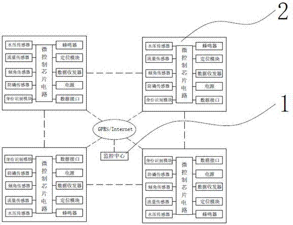
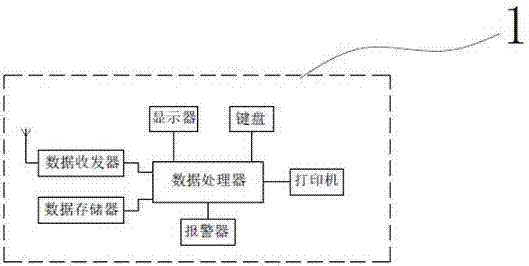
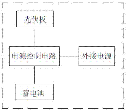
[0021] Such as Figure 1~5 As shown, a water pressure monitoring device includes a fire hydrant 16, a detector 2 installed on the fire hydrant 16, a monitoring center 1 connected to the detector 2. The detector 2 is connected to the monitoring center 1 through a wireless network, and the monitoring center 1 Including a data processor and a display, the data processor is connected with a display, a keyboard, a printer, an alarm, a data memory and a data transceiver, the detector 2 includes a micro-control chip circuit, and the micro-control chip circuit is connected with a water pressure sensor, a flow sensor, Inclination sensor, tamper-proof sensor, identity recognition module, buzzer, positioning module, data transceiver, power supply and data interface. The power supply includes a power control circuit. The power control circuit is connected to a photovoltaic panel, a battery and an external power supply. The battery is lead-acid Battery, battery electrolyte is composed of the following components and parts by weight: 0.1~1 part of carboxymethyl cellulose, 0.2~6 parts of fumed silica, 0.05~1.5 parts of phosphoric acid, 0.01~0.03 parts of ethylene bis-stearamide , PTFE emulsion 0.05~0.5 part, anhydrous sodium sulfate 0.5~2 part, 1,2-propylene glycol 0.02~0.05 part, stannous sulfate 0.01~1 part, polyethylene emulsion 0.02~0.2 part, sulfuric acid 35~50 Parts, 40-60 parts deionized water.
[0022] The detector 2 of the present invention can prevent the fire hydrant 16 from taking water abnormally. It can also alarm and display the location of the damaged fire hydrant 16 when the fire hydrant 16 is deliberately damaged, knocked down, or illegally displaced. The water pressure and flow rate of the fire hydrant 16 equipped with the detector 2 and the safety status of the fire hydrant 16, the grid of the battery used is not easy to corrode, the self-discharge rate of the battery is low, ethylene bis stearic acid amide and 1,2-propanediol Through polyethylene milk, stannous sulfate or due to the synergistic effect, unexpected effects are produced, which promotes the high temperature resistance, low temperature resistance, charging resistance, saturation and charging acceptance of the battery, the electrolyte is not easy to volatilize, and the antifreeze effect is good. Long cycle life.
[0023] The water pressure sensor is installed on the water-stop pad 9 at the lower end of the fire hydrant 16, and the tamper-proof sensor 12 is composed of the dry reed switch 13 on the fire hydrant 16 and the permanent reed switch 13 on the stem 15 of the fire hydrant. The reed switch 13 of the anti-pry sensor 12 is normally closed. When the fire hydrant 16 is destroyed, the anti-pry sensor 12 will be activated and the information will be transmitted to the micro-control chip circuit to start the buzzer, which can warn of abnormal opening Or thief, and attract the attention of surrounding people to prevent the situation from getting worse.
[0024] The middle of the fire hydrant 16 is provided with a mounting base 10, the upper and lower ends of the mounting base are provided with flanges 5 and 6 to connect to each other, the detector 1 is connected to the mounting base 10, and the distance between the mounting base 10 and the bottom of the fire hydrant 16 is the total length of the fire hydrant 16 1/5~2/5, the detector 2 can be installed on the fire hydrant 16, and the location is not obvious, which is not easy to cause illegal thieves to detect. The installation position of the detector 2 is not easy to be hit, which can protect the detector 2.
[0025] The mounting base 10 is ring-shaped, and the diameter ratio of the mounting base 10 to the fire hydrant 16 is 1.1~1.3:1, so that the detector 2 is more securely and firmly installed on the fire hydrant 16, and the mounting base 10 has a higher tightness.
[0026] The thickness of the flange 5 or 6 is 1/3~1/2 of the thickness of the mounting base 10, which can improve the rigidity and tightness of the mounting base 10, and it is convenient to disassemble and assemble the mounting base 10, making the mounting base 10 difficult to contact with the fire hydrant 16 Even if the fire hydrant 16 is damaged, the mounting seat 10 will not easily fall off.

Example Embodiment

[0027] Example 2:
[0028] Such as Figure 1~5 As shown, a water pressure monitoring device includes a fire hydrant 16, a detector 2 installed on the fire hydrant 16, a monitoring center 1 connected to the detector 2. The detector 2 is connected to the monitoring center 1 through a wireless network, and the monitoring center 1 Including a data processor and a display, the data processor is connected with a display, a keyboard, a printer, an alarm, a data memory and a data transceiver, the detector 2 includes a micro-control chip circuit, and the micro-control chip circuit is connected with a water pressure sensor, a flow sensor, Inclination sensor, tamper-proof sensor, identity recognition module, buzzer, positioning module, data transceiver, power supply and data interface. The power supply includes a power control circuit. The power control circuit is connected to a photovoltaic panel, a battery and an external power supply. The battery is lead-acid Battery, the battery electrolyte is composed of the following components and preferred parts by weight: 0.3 parts of carboxymethyl cellulose, 2 parts of fumed silica, 1.1 parts of phosphoric acid, 0.02 parts of ethylene bisstearic acid amide, and 0.2 parts of polytetrafluoroethylene emulsion. Parts, 1 part of anhydrous sodium sulfate, 0.03 parts of 1,2-propylene glycol, 0.08 parts of stannous sulfate, 0.09 parts of polyethylene milk, 42 ​​parts of sulfuric acid, 48 parts of deionized water, the water pressure sensor is installed at the lower end of the fire hydrant 16 On the water cushion 9, the anti-tamper sensor 12 is composed of a reed switch 13 on the fire hydrant 16 and a permanent magnet 4 arranged on the valve stem 15 of the fire hydrant for working with the reed switch 13. Base 10, the upper and lower ends of the mounting base are provided with flanges 5 and 6 to connect to each other. The detector 1 is connected to the mounting base 10. The distance between the mounting base 10 and the bottom of the fire hydrant 16 is preferably 3/10 of the total length of the fire hydrant 16. 10 is a ring shape, the diameter ratio of the mounting base 10 to the fire hydrant 16 is preferably 1.2:1, and the thickness of the flange 5 or 6 is preferably 1/2 of the thickness of the mounting base 10.
[0029] The above-mentioned connection or conventional technologies, such as wireless transmission technology, solar light source conversion technology, GPRS positioning technology, etc. are currently known technologies, so they will not be described in detail here.
[0030] The diameter ratio of the mounting base 10 to the fire hydrant 16 is not limited to 1.1~1.3:1, but should also include the diameter ratio of the mounting base 10 to the fire hydrant 16 of 1.1:1 or 1.11:1 or 1.12:1 or 1.13:1 or 1.14: 1...or 1.29:1 or 1.30:1.
[0031] The thickness of the flange 5 or 6 is not limited to 1/3~1/2 of the thickness of the mounting seat 10, but also includes the thickness of the flange 5 or 6 which is 20/60 or 21/60 or 22/60 of the thickness of the mounting seat 10. 23/60...or 29/60 or 30/60.
[0032] Preparation of electrolyte for storage battery of the present invention:
[0033] (1) Inject 500-550 kg of deionized water into the special tank or barrel of polynuclear silicate electrolyte;
[0034] (2) At the same time, turn on the stirring pump or air stirring device, and control the speed to be 800 rpm ~ 2500 rpm, and then slowly add the target electrolyte weight to the special tank or barrel of polynuclear silicate electrolyte. The percentage content is 0.01%-1.0% stannous sulfate, the weight percentage content is 0.5%-2.0% anhydrous sodium sulfate and the weight percentage content is 0.01~0.03% ethylene bis-stearic acid amide and the weight percentage content is 0.02 ~0.05% of 1,2-Propanediol, then let it stir and dissolve fully and evenly, the time is 25-35 minutes;
[0035] (3) Then add the fumed silica and carboxymethyl cellulose in the target electrolyte to 0.5%-5.0% and 0.1%-1.0% by weight respectively to the special polynuclear silicate electrolyte. In the tank or barrel, the time interval for adding is 5~10 minutes, and continue to stir for 25~35 minutes after adding all;
[0036] (4) Turn on the cooling system, and slowly add the weighed 450-500 kg of concentrated sulfuric acid 3 to 5 times into the special tank or barrel of the polynuclear silicate electrolyte. After each addition, measure the temperature and control the temperature at 60 ~72℃, after all the additions, continue to stir, when the temperature drops to 40~50℃, proceed to the next step;
[0037] (5) Slowly add a polytetrafluoroethylene emulsion with a weight percentage of 0.05~0.5% and a polyethylene emulsion with a weight percentage of 0.02~0.2% into the special tank or barrel of the polynuclear silica electrolyte. And phosphoric acid with a content of 0.05~1.5% by weight, and then let it stir thoroughly and evenly until the temperature drops to room temperature, and the electrolyte is obtained;
[0038] (6) Mix the prepared electrolyte with the diluted sulfuric acid electrolyte with a density of 1.320 g/cm3~1.335g/cm3 at 25°C in a certain proportion, stir for 25~35 minutes after mixing, and measure the electrolyte content in the electrolyte. The percentage content of sulfuric acid is controlled between 43.0~44.0%, which completes the preparation of lead-acid battery electrolyte.
[0039] The invention uses a green solar source to supply power to the monitoring device, which is environmentally friendly, the battery grid used is not easy to corrode, the self-discharge rate of the battery is low, and the battery has high temperature resistance, low temperature resistance, charging resistance, saturation and charging acceptance performance, and electrolysis The liquid is not easy to volatilize, the anti-freezing effect is good, and the battery has a long cycle life, so that the detector 2 can keep running for 24 hours, which improves the safety and stability of the water pressure monitoring device.

Example Embodiment

[0040] Example 3:
[0041] The actual use of the water pressure monitoring device of the present invention:
[0042] Such as Figure 1~5 As shown, when the management and maintenance personnel want to inspect the fire hydrant 16, they need to carry a proximity card containing personal information. The identity recognition module set on the fire hydrant 16 will automatically instruct the detector 2 to disarm and upload relevant information to Monitoring center 1, monitoring center 1 displays the information of the patrol personnel, the patrol time, the number of the fire hydrant 16 and the area where the inspection is completed. After the personnel leave, the identification module cannot search for the proximity card signal within 3 minutes, and then the detector 2 It will automatically re-arm and upload the armed information to the monitoring center 1. You can add a short-distance swiping card sign-in device as needed to realize inspection sign-in and attendance. The monitoring center 1 can monitor the corresponding inspection sign-in personnel information, time, and fire hydrant number in real time , Route, area and other information, the monitoring center 1 can remotely arm and disarm or authorize the opening according to the request or information of the on-site staff. Once a fire occurs, enter the corresponding fire address, and the electronic map of the monitoring center 1 will automatically display Information about the surrounding fire hydrants 16 and commanders can pick out the appropriate fire hydrants 16, automatically formulate the best driving route, and remotely authorize disarming in advance.
[0043] The reed switch 13 of the tamper-proof sensor in the fire hydrant 16 is normally closed. When the water outlet switch is turned off without authorization to take water or is forced to turn off the water outlet switch, valuable parts of the fire hydrant 16 and the valve in the fire hydrant 16 are stolen. The rod will rise, and the permanent magnet 4 will rise, and it will be separated from the reed switch 13 of the tamper-proof sensor. The dry reed switch 13 is in the disconnected state, and the tamper-proof sensor is pushed, and the micro-control chip will start the high-pitched buzzer. The device emits a harsh buzzing sound, and at the same time, reports the alarm to the monitoring center 1, so that it can warn or scare people who open it abnormally or thief, and prevent the situation from getting worse.
[0044] The monitoring center 1 can assign relevant processing according to the various information uploaded in real time by each fire hydrant 16, such as notifying the water company to pressurize if the water pressure is not enough, and the water flow sensor prompts water leakage to notify the patrol personnel to check and prevent water leakage again. The tamper-proof sensor and the water flow sensor jointly indicate that the water has been taken abnormally, and the manager will be notified to stop it.

PUM

PropertyMeasurementUnit
Density1.32 ~ 1.335g/cm³
tensileMPa
Particle sizePa
strength10

Description & Claims & Application Information

We can also present the details of the Description, Claims and Application information to help users get a comprehensive understanding of the technical details of the patent, such as background art, summary of invention, brief description of drawings, description of embodiments, and other original content. On the other hand, users can also determine the specific scope of protection of the technology through the list of claims; as well as understand the changes in the life cycle of the technology with the presentation of the patent timeline. Login to view more.

Similar technology patents

Aqueous ion battery and preparation method thereof

ActiveCN111430819AInhibit corrosionLow self-discharge rateFinal product manufactureNegative electrodesChemical activityCharge and discharge
Owner:北京恩力动力科技有限公司 +2

Load type ferrate electrode active material and method of manufacturing the same

InactiveCN101369655ALow self-discharge rateImprove rate discharge performanceHybrid capacitor electrodesCapacitor electrodesChemistryHigh rate
Owner:NANKAI UNIV

Lithium-rich manganese-based material and application method thereof

PendingCN113716621AImprove high temperature cycle lifeLow self-discharge rateSecondary cellsPositive electrodesElectrical batteryLithium electrode
Owner:安徽博石高科新材料股份有限公司

Classification and recommendation of technical efficacy words

  • Strong performance
  • Low self-discharge rate

Saloon car tyre surface

Owner:QINGDAO YELLOWSEA RUBBER

Embedded video playing device based on the dual processor

InactiveCN101009836AStrong performanceFacilitate reuse of hardware and software resourcesPulse modulation television signal transmissionDigital video signal modificationDsp processorHigh complexity
Owner:ZHEJIANG UNIV

Home-made automatic embedded computer system and display card driving method thereof

ActiveCN104360860AStrong performanceImprove human-computer interaction performance and graphics display and control performanceSpecific program execution arrangementsInstructions per secondGraphics
Owner:湖南长城科技信息有限公司 +1

Electric double layer capacitor

InactiveUS6299790B1Low self-discharge rateReduce incidenceSolid electrolytesHybrid capacitor electrolytesHydrogen compoundsSolvent
Owner:DAI ICHI KOGYO SEIYAKU CO LTD

Li-ion secondary battery with double standard cells

InactiveUS20050042504A1Light weightLow self-discharge ratePrimary cell to battery groupingFinal product manufactureIonStandard cell
Owner:ALTEK CORP
Why Eureka
Try Eureka