Automatic placement machine

A technology for placement machines and racks, which is applied to mechanical equipment, conveyor objects, connecting components, etc., can solve the problems of high labor intensity, affect physical health, and uneven attachment, so as to reduce labor intensity and improve stickers. Film speed and efficiency, improve the effect of attaching effect

Active Publication Date: 2022-08-09
贵州群华九九特种陶瓷科技有限公司
View PDF0 Cites 0 Cited by
  • Summary
  • Abstract
  • Description
  • Claims
  • Application Information

AI Technical Summary

Problems solved by technology

At present, the above process is mainly realized by manual operation, and its shortcomings are obvious: high labor intensity, low work efficiency, uneven attachment, and paraffin produces peculiar smell, which affects health

Method used


Image

  • Automatic placement machine
  • Automatic placement machine
  • Automatic placement machine

Examples


Embodiment 1

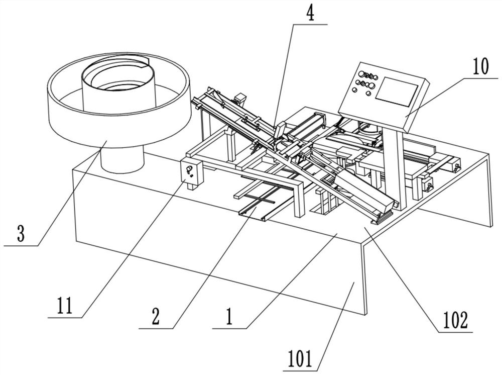
[0046] Example 1: as Figure 1 to Figure 3 As shown, the automatic placement machine of this embodiment includes:

[0047] Frame 1, the frame 1 is provided with iron plate conveying guide rails 2; the frame 1 includes support legs 101 and a support platform 102, the iron plate conveying guide rail 2 is fixed on the supporting platform 102, and the iron plate conveying guide rail 2 is used for conveying iron plates. 100;

[0048] The vibration conveying device 3 is used to transport the valve plate 200 according to a certain attitude after arranging the valve plate 200; the vibration conveying device 3 is a vibration screening device to ensure that the valve plate is always conveyed with the attitude of the surface to be polished upward; The screening equipment belongs to the conventional screening and feeding equipment, so the present invention is figure 1 is just a simple indication;

[0049] The shaking arrangement device 4 is installed on the frame 1, specifically above ...

Embodiment 2

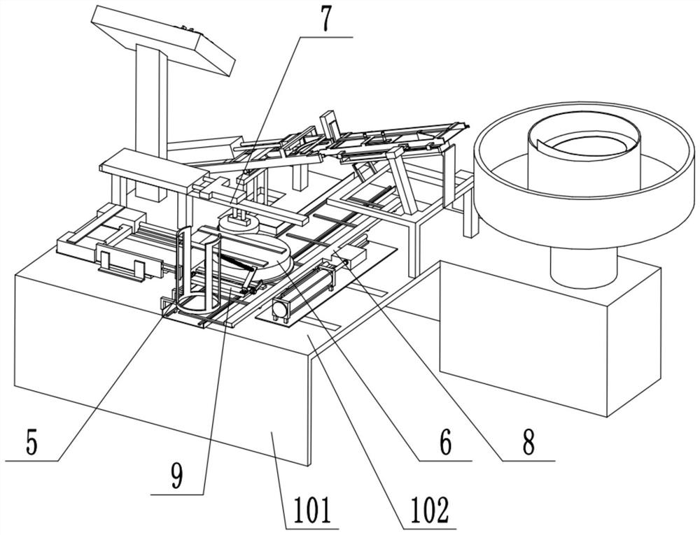
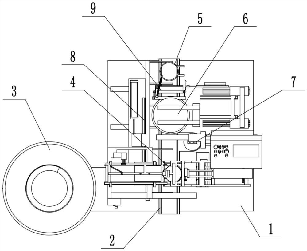
[0056] Embodiment 2: as the preferred embodiment of embodiment 1, as Figure 4 As shown, the shaking finishing device 4 includes a shaking unloading device 41 and a material receiving and attaching device 42; Figure 5 to Figure 7 As shown, the shaking feeding device 41 includes a feeding chute 4102 installed obliquely on the frame 1 through a bracket 4101. A movable bottom plate 4103 is installed in the feeding chute 4102, and the movable bottom plate 4103 can move back and forth in the feeding chute 4102 to remove The valve plate falling on the surface of the movable bottom plate 4103 is conveyed downward, and a stopper device 43 is provided near the lower end of the discharge chute 4102. The movable bottom plate 4103 is driven by the bottom plate cylinder 4109 installed on the bracket 4101. The test shows that the movement of the movable bottom plate 4103 When the direction is perpendicular to the feeding direction of the feeding chute 4102, the guiding effect of the valve ...

Embodiment 3

[0057] Embodiment 3: As a preference of Embodiment 2, the test shows that after the valve plate output from the vibrating conveying device 3 enters the feeding chute 4102, in most cases, the valve plate is concentrated on one side of the positioning ring 4205, so that the It is difficult to evenly fill the valve plate in the ring cavity of the positioning ring 4205. Therefore, in order to improve the uniformity of the material guide, a material guide component is provided in the shaking and unloading device 41, such as Figure 4 to Figure 6 As shown, the material guide assembly includes a material guide plate 4104 inclined along the width direction of the feeding chute 4102 and a fixed shutter 4105 fixed in the feeding chute 4102 and located above the movable bottom plate 4103, the material guiding plate 4104 and the fixed shutter The 4105 is fixedly connected with the feeding chute 4102 through the fixing frame 4106, and the feeding plate 4104 is located at the front end of t...


PUM


Abstract

The invention relates to an automatic placement machine, which replaces the traditional manual placement, and mainly comprises: a frame, on which an iron plate conveying guide rail is arranged; posture conveying; shaking arrangement device, installed on the frame, connected with the output end of the vibration conveying device, used to arrange the valve plate into a disc shape, so as to centrally place the valve plate on the iron plate; iron plate storage device, Used for stacking and storing iron plates; iron plate heating device, covering the top of the iron plate conveying rail and set close to the iron plate storage device; paraffin melting and coating device, used to coat the molten paraffin on the surface of the iron plate; iron plate conveying The device is used to push the iron plate from the iron plate storage device to the iron plate heating device, the paraffin melting coating device and the shaking finishing device. The invention replaces the traditional manual patch operation, reduces labor intensity, improves patch speed and efficiency, and improves patch quality.

Description

technical field [0001] The invention relates to the field of electronic ceramic equipment, in particular to chip equipment for electronic ceramics. Background technique [0002] Electronic ceramics refer to ceramics that can utilize electrical and magnetic properties in the electronics industry. Electronic ceramics are ceramics with new functions that are finally obtained through precise control of the surface, grain boundaries and dimensional structure. It can be widely used in energy, household appliances, automobiles, etc. [0003] Known special ceramic manufacturing technologies, such as isostatic pressing, dry pressing, hot pressure injection molding, grouting, injection molding, in-situ injection molding, etc., now, in the industrial mass production process, the most economical and The most are hot-pressure injection molding and injection molding process, and my country's hot-pressure injection molding process accounts for more than 70% of the production capacity of s...

Claims


Application Information

Patent Timeline
Patent Type & Authority Patents(China)
IPC IPC(8): B65G47/14F16B11/00
CPCF16B11/006
Inventor 陈代兴张南泉
Owner 贵州群华九九特种陶瓷科技有限公司
Why Eureka
Try Eureka