Terahertz imaging system based on photonics technology

A terahertz imaging and photonics technology, applied in the field of terahertz imaging, can solve the problems of increased system cost, low energy utilization rate, easy to burn out detectors, etc., to achieve not easy to damage devices, high energy utilization rate, and improve imaging quality effect

Active Publication Date: 2017-08-01
SHANGHAI INST OF MICROSYSTEM & INFORMATION TECH CHINESE ACAD OF SCI
View PDF5 Cites 6 Cited by
  • Summary
  • Abstract
  • Description
  • Claims
  • Application Information

AI Technical Summary

Problems solved by technology

In the scheme of using double laser beat frequency as the light source, the wavelength of the two lasers is adjusted so that the interval between them is the required terahertz frequency, but since only a single frequency terahertz signal is generated, it is equivalent to a monochromatic light source, terahertz After the wave is emitted, due to the reflection of the lens or mirror in the optical path and the surface of the object to be measured, interference effects will occur, resulting in poor imaging quality, unclear and blurred boundaries
Figure 1 shows the use of double laser beat frequency as light source The imaging result of the object to be tested here is a wrench placed in a thick cardboard box. Due to the interference effect caused by the monochromatic light source, the interference fringes in the background are obvious, and the boun

Method used


Image

  • Terahertz imaging system based on photonics technology
  • Terahertz imaging system based on photonics technology
  • Terahertz imaging system based on photonics technology

Examples


Embodiment Construction

[0031] Below in conjunction with specific embodiment, further illustrate the present invention. It should be understood that these examples are only used to illustrate the present invention and are not intended to limit the scope of the present invention. In addition, it should be understood that after reading the teachings of the present invention, those skilled in the art can make various changes or modifications to the present invention, and these equivalent forms also fall within the scope defined by the appended claims of the present application.

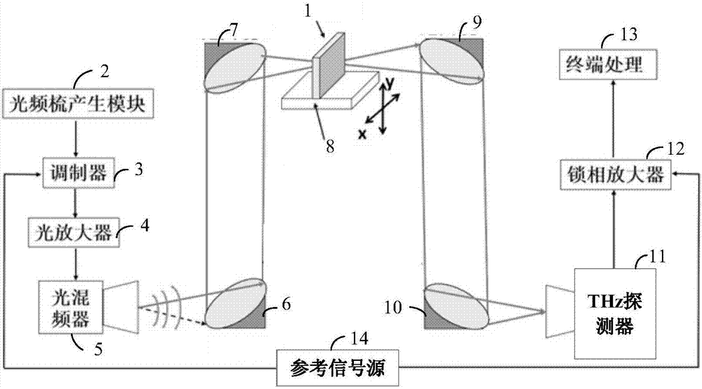
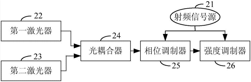
[0032] see Figure 2 to Figure 4 . It should be noted that the diagrams provided in this embodiment are only schematically illustrating the basic idea of ​​the present invention, and only the components related to the present invention are shown in the diagrams rather than the number, shape and shape of the components in actual implementation. Dimensional drawing, the type, quantity and proportion of each component can be cha...


PUM


Abstract

The invention provides a terahertz imaging system based on a photonics technology. The terahertz imaging system comprises an optical frequency comb generation module, an optical mixer module, a scanning module, a mobile platform, a focusing module, a terahertz detector module and a terminal processing module, wherein the optical frequency comb generation module can generate optical beat frequency signals, the optical mixer module can convert the optical beat frequency signals into terahertz signals, the scanning module can collimate the terahertz signals and gather the terahertz signals on an article to be measured, the mobile platform can drive the article to be measured to move, the focusing module can gather terahertz signals scattered from the article to be measured, the terahertz detector module can convert the terahertz signals into electrical signals, and the terminal processing module can obtain a two-dimensional image of the article to be measured according to the electric signals. As the terahertz imaging system disclosed by the invention utilizes the optical frequency comb generation module as a light source, and the interference phenomenon in the image is eliminated, imaging quality is obviously improved; meanwhile, required luminous power is smaller than 30 percent of an erbium-doped optical fiber amplifier source imaging system, so that cost of the system is greatly reduced.

Description

technical field [0001] The present invention relates to the field of terahertz imaging, in particular to a terahertz imaging system based on photonics technology. Background technique [0002] Terahertz (hereinafter referred to as THz, 1THz=10 12 Hz) band refers to the electromagnetic spectrum region in the electromagnetic spectrum with frequencies from 100 GHz to 10 THz. Because THz waves have good penetrating power and are harmless to the human body, THz imaging has great application prospects in security inspection, express package inspection, and medical imaging. [0003] The THz imaging system based on photonics technology is composed of commonly used optical communication devices, generally including lasers, modulators, photodetectors, etc. It uses photodetectors to convert laser signals into terahertz signals for emission, and the performance of the devices is stable and cheap. At the same time, due to the extremely low loss of the signal in the optical fiber, the s...

Claims


Application Information

Patent Timeline
IPC IPC(8): G01N21/3581
CPCG01N21/3581
Inventor 姚辰张戎周涛曹俊诚
Owner SHANGHAI INST OF MICROSYSTEM & INFORMATION TECH CHINESE ACAD OF SCI
Why Eureka
Try Eureka