Low-rigidity magnetic suspension gravity compensator and micro stage structure

A gravity compensation and magnetic levitation technology, applied in the field of gravity compensation structure, can solve the problem of high normal stiffness, achieve good vibration reduction and vibration isolation effects, simple structure, and wide application range.

Active Publication Date: 2017-08-01
HUAZHONG UNIV OF SCI & TECH
View PDF5 Cites 11 Cited by
  • Summary
  • Abstract
  • Description
  • Claims
  • Application Information

AI Technical Summary

Problems solved by technology

[0004] At present, those skilled in the art have done some research. For example, the patent CN104847825A discloses an array type magnetic levitation gravity compensator. The array type magnetic levitation gravity compensator includes two stator structures and a mover structure. The mover structure exerts magnetic attraction force and magnetic repulsion force on the mover mechanism from the upper and lower sides of the mover structure respectively to realize the gravity compensation of the mover structure; however, the array type maglev gravity compensator higher normal stiffness

Method used


Image

  • Low-rigidity magnetic suspension gravity compensator and micro stage structure
  • Low-rigidity magnetic suspension gravity compensator and micro stage structure
  • Low-rigidity magnetic suspension gravity compensator and micro stage structure

Examples


Embodiment Construction

[0031] In order to make the object, technical solution and advantages of the present invention clearer, the present invention will be further described in detail below in conjunction with the accompanying drawings and embodiments. It should be understood that the specific embodiments described here are only used to explain the present invention, not to limit the present invention. In addition, the technical features involved in the various embodiments of the present invention described below can be combined with each other as long as they do not constitute a conflict with each other.

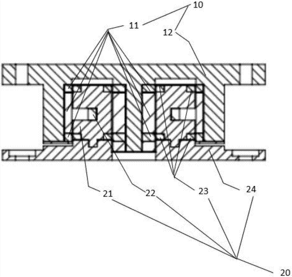
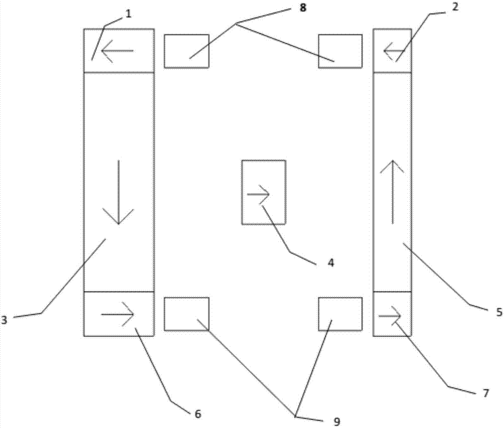
[0032] see figure 1 and figure 2 , the low-stiffness magnetic levitation gravity compensator provided by the preferred embodiment of the present invention, the magnetic levitation gravity compensator includes a mover structure 10 and a stator structure 20, and the stator structure 20 is separated from the upper and lower sides of the mover structure 10 respectively. Both sides exert magnetic ...


PUM

PropertyMeasurementUnit
thicknessaaaaaaaaaa
thicknessaaaaaaaaaa
heightaaaaaaaaaa

Abstract

The invention belongs to the technical field of a relevant gravity compensation structure and discloses a low-rigidity magnetic suspension gravity compensator. The low-rigidity magnetic suspension gravity compensator comprises a rotor structure and a stator structure, wherein the rotor structure comprises an external permanent-magnet array ring, an internal permanent-magnet array ring and a rotor support frame, wherein the external permanent-magnet array ring and the internal permanent-magnet array ring are respectively arranged at two opposite side walls of an annular groove of the rotor support frame, the thickness of the internal permanent-magnet array ring is larger than the thickness of the external permanent-magnet array ring, the stator structure comprises a coil support and a stator permanent-magnet ring, the coil support is accommodated in the annular groove, the stator permanent-magnet ring is embedded onto the coil support, the height of the stator permanent-magnet ring is larger than the thickness thereof, and the distance between the stator permanent-magnet ring and the internal permanent-magnet array ring is smaller than the distance between the stator permanent-magnet ring and the external permanent-magnet array ring. The invention also provides a micro stage structure comprising the magnetic suspension gravity compensator. By the magnetic suspension gravity compensator, near-zero rigidity magnetic suspension of the rotor structure within a relatively wide movement range is achieved; and moreover, the magnetic suspension gravity compensator is simple in structure and wide in application range.

Description

technical field [0001] The invention belongs to the technical field related to gravity compensation structures, and more specifically relates to a low-rigidity magnetic levitation gravity compensator and a micro-motion stage structure. Background technique [0002] In many advanced industrial equipment, it is necessary to realize the six-degree-of-freedom movement of moving parts and perform precise positioning on them, such as mask tables and workpiece tables in lithography machines, among which Z-direction actuators mostly use Lorentz coils Or electromagnets, which use Lorentz force or magnetic resistance to control the normal deflection and pitch deflection of the moving parts respectively. For the ultra-precise positioning workpiece table in the lithography machine, how to protect the micro-motion table part carrying the silicon wafer from the interference caused by the vibration of the basic frame during the exposure process is very important, so the vibration reduction...

Claims


Application Information

Patent Timeline
Patent Type & Authority Applications(China)
IPC IPC(8): G03F7/20
CPCG03F7/70716G03F7/70808
Inventor 陈学东陈冬郎曾理湛赵鹏程胡兰雄
Owner HUAZHONG UNIV OF SCI & TECH
Why Eureka
Try Eureka