Magnetic levitation gravity compensator with alternately arranged stator magnets

A technology of gravity compensation and staggered arrangement, applied in the direction of magnetic attraction or thrust holding device, electrical components, etc., can solve the problem of high stiffness of gravity compensator

Active Publication Date: 2018-01-09
HUAZHONG UNIV OF SCI & TECH
View PDF6 Cites 3 Cited by
  • Summary
  • Abstract
  • Description
  • Claims
  • Application Information

AI Technical Summary

Problems solved by technology

[0004] In view of the above defects or improvement needs of the prior art, the present invention provides a magnetic levitation gravity compensator in which the stator magnets are staggered. Through the staggered arrangement of the magnets of the permanent magnet stator, two sets of levitation forces in opposite directions are formed, so that the stator The formed two sets of stiffness approximately cancel each other, thereby solving the technical problem of high stiffness of the gravity compensator

Method used


Image

  • Magnetic levitation gravity compensator with alternately arranged stator magnets
  • Magnetic levitation gravity compensator with alternately arranged stator magnets
  • Magnetic levitation gravity compensator with alternately arranged stator magnets

Examples


Embodiment Construction

[0025] In order to make the object, technical solution and advantages of the present invention clearer, the present invention will be further described in detail below in conjunction with the accompanying drawings and embodiments. It should be understood that the specific embodiments described here are only used to explain the present invention, not to limit the present invention. In addition, the technical features involved in the various embodiments of the present invention described below can be combined with each other as long as they do not constitute a conflict with each other.

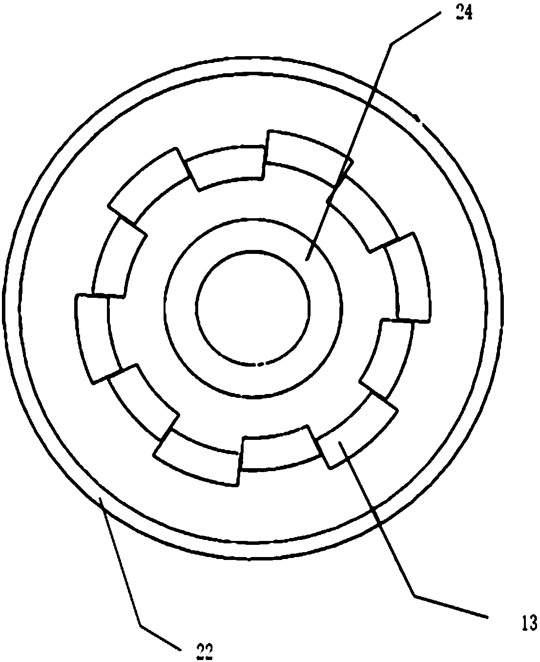
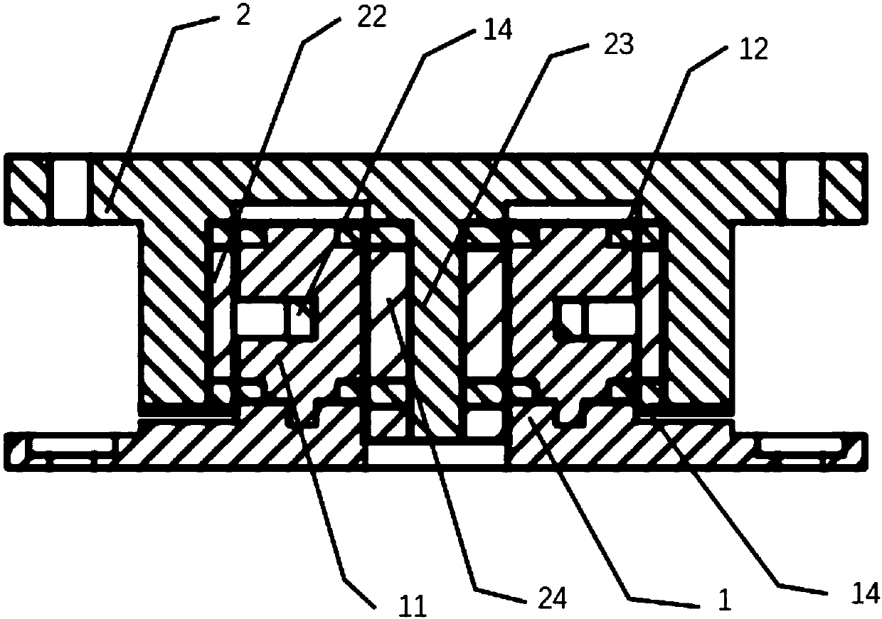
[0026] figure 1 It is a top view of the stator and the stator of the magnetic levitation gravity compensator constructed according to the preferred embodiment of the present invention, figure 2 It is a sectional view of the magnetic levitation gravity compensator constructed according to the preferred embodiment of the present invention, as figure 1 and 2 As shown, the gravity compensator in...


PUM


Abstract

The invention belongs to the field of a gravity compensator, and discloses a magnetic levitation gravity compensator with alternately arranged stator magnets. The gravity compensator comprises an upper die and a lower die; a groove is formed in the upper die; an outer mover in permanent magnet array magnetic ring configuration is arranged on the inner side wall of the groove; a convex column is also arranged in the center of the groove; an inner mover in permanent magnet array magnetic ring configuration corresponding to the outer mover is arranged on the outer surface of the convex column; alug boss matched with the groove is arranged on the lower die; an upper end coil, an annular permanent magnet stator and a lower end coil are arranged on the outer surface of the lug boss from the topto bottom in sequence; the permanent magnet stator is equally divided into multiple arc-shaped permanent magnets in the circumferential direction; the adjacent two arc-shaped permanent magnets are arranged in a staggered manner front and back; and the radius length difference of the adjacent two arc-shaped permanent magnets is less than the thickness of the permanent magnet stator. By virtue of the magnetic levitation gravity compensator, near-zero-rigidity magnetic levitation of the movers within the working range is realized; and meanwhile, the magnetic levitation gravity compensator is simple in structure, suitable for instruments needing low vibration and high precision, and wide in applicable range.

Description

technical field [0001] The invention belongs to the field of gravity compensators, and more specifically relates to a magnetic levitation gravity compensator in which stator magnets are staggered. Background technique [0002] The high-precision platform is an extremely important part in the fields of precision machining, integrated circuit engineering and precision component manufacturing. Taking the lithography equipment manufactured by Seiko as an example, as the integration of large-scale inherited circuit devices continues to increase, the resolution of lithography processing continues to increase, and the lithography system’s requirements for the control accuracy of each degree of freedom of the precision motion platform are also constantly increasing. promote. For the ultra-precise positioning workpiece stage in the lithography machine, how to prevent the micro-movement stage components carrying the silicon wafer from the interference caused by the vibration of the b...

Claims


Application Information

Patent Timeline
Patent Type & Authority Applications(China)
IPC IPC(8): H02N15/00
Inventor 陈学东曾理湛陈冬郎胡兰雄赵鹏程
Owner HUAZHONG UNIV OF SCI & TECH
Why Eureka
Try Eureka