Unlock instant, AI-driven research and patent intelligence for your innovation.

Power conversion device

A technology of a power conversion device and a judging device, which is applied in the direction of controlling electromechanical transmission devices, measuring devices, and measuring electrical variables, etc., can solve the problems of inability to disconnect the state and inability to detect bad connections, and achieve the effect of increasing the cost of the device

Active Publication Date: 2017-08-01
HITACHI LTD
View PDF7 Cites 7 Cited by
  • Summary
  • Abstract
  • Description
  • Claims
  • Application Information

AI Technical Summary

Problems solved by technology

[0009] In a system in which a plurality of, for example, four induction motors are connected in parallel to one inverter device under vector control and are driven, three of the four induction motors are out of phase due to poor connection, and only one of them is connected. If the wiring between the induction motors is sound, the equivalent circuit configuration is the same as that of the drive system for controlling one induction motor described in Patent Document 1, so even if the disconnection detection device described in Patent Document 1 is applied Even in a system where four induction motors are connected in parallel and driven, it is impossible to detect such connection failures.
[0010] In addition, in Document 2, it is a technique to calculate the torque output from the induction motor and to detect the disconnection state of one induction motor based on the fluctuation of the output torque. In the case of feedback control in which the output torque fluctuation is reduced by matching the torque command value with each other, the disconnection state cannot be detected with high accuracy.

Method used


Image

  • Power conversion device
  • Power conversion device
  • Power conversion device

Examples


Embodiment Construction

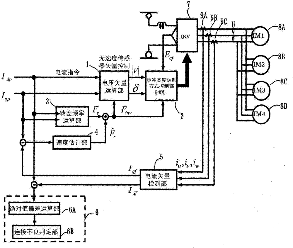
[0041] figure 1 A control block diagram of the drive control device for a railway vehicle in the first embodiment of the present invention is shown. Such as figure 1 As shown, DC power obtained from overhead lines via a pantograph is supplied to the inverter device 7 , and four induction motors 8A, 8B, 8C, and 8D are connected to the AC side of the inverter device 7 . These four induction motors 8A, 8B, 8C, and 8D are connected in parallel with each other, and vector control is performed by one inverter device 7 . The switching elements provided inside the inverter device 7 are switched based on the gate signal output from the pulse width modulation system control unit (PWM control unit) 2, thereby switching the four induction motors connected in parallel to the inverter device 7 8A, 8B, 8C, 8D provide the desired AC power.

[0042] The drive control device in this embodiment includes: a voltage vector calculation unit 1 that outputs a voltage command value and phase comman...


PUM


Abstract

In a system that one inverter control apparatus drives a plurality of sensing motors and is subjected to sensor-less vector control, a state of default phase or false wiring of a motor cannot be detected with excellent precision. A power conversion device includes: a current vector detecting unit that generates a torque current detection value and an exciting current detection value from a current detection value between the power conversion device and the plurality of induction motors; a slip frequency calculating unit that generates a slip frequency on the basis of a torque current command value and an exciting current command value; a speed estimating unit that generates an estimation speed of the induction motor on the basis of a deviation between the torque current detection value and the torque current command value; a connection failure detecting device that detects a connection failure of the plurality of induction motors on the basis of the exciting current detection value; and a voltage vector calculation unit that generates a voltage command value on the basis of an inverter frequency generated on the basis of the slip frequency and the estimation speed such that the torque current detection value follows the torque current command value, the torque current command value, and the exciting current command value.

Description

technical field [0001] The present invention relates to a railway vehicle drive control device, and more particularly to a railway vehicle power conversion device having a function of detecting an abnormal state of a load motor in a drive system that supplies three-phase AC power to a motor from a power conversion device. Background technique [0002] As a method of detecting a phase loss of the output of an inverter device driving one load motor, Patent Document 1 discloses that by detecting the absolute value of the deviation between the Q-axis current command and the Q-axis current output, or by detecting the difference between the D-axis current command and the Q-axis current output. The absolute value of the deviation of the D-axis current output is used to perform the protection action. [0003] In addition, Patent Document 2 discloses a technique in which a torque fluctuation exceeding a predetermined time span is performed in a system in which a plurality of inductio...

Claims


Application Information

Patent Timeline
IPC IPC(8): H02P27/08H02P21/24H02P21/18G01R31/04
CPCG01R31/67H02P27/085H02H3/13H02P21/18H02P27/06H02P29/032
Inventor 立原周一夏永强
Owner HITACHI LTD
Features
  • R&D
  • Intellectual Property
  • Life Sciences
  • Materials
  • Tech Scout
  • Unparalleled Data Quality
  • Higher Quality Content
  • 60% Fewer Hallucinations
Learn More