Crankshaft-driven-piston type molecular sieve oxygen production system

A technology of crankshaft drive and oxygen production system, which is applied in the fields of oxygen preparation, specific gas purification/separation, oxygen/ozone/oxide/hydroxide, etc. down, unable to achieve miniaturization and low energy consumption and other problems, to achieve the effect of low power, simple structure and flexible use

Pending Publication Date: 2017-08-04
洲利实业(上海)有限公司
View PDF0 Cites 6 Cited by
  • Summary
  • Abstract
  • Description
  • Claims
  • Application Information

AI Technical Summary

Problems solved by technology

[0002] Modern commonly used oxygen production methods include: cryogenic method, molecular sieve pressure swing adsorption method, membrane method and Wei Boqing’s magnetic separation method. The most energy-saving oxygen production method here is Wei Boqing’s magnetic separation method, but the magnetic separation method cannot be industrialized yet. , while the cryogenic method and the molecular sieve pressure swing adsorption method cannot achieve miniaturization and low energy consumption, and membrane oxygen production can help miniaturization, but the cost and energy consumption still cannot be reduced; Oxygen generators for office and home use, low energy consumption, low noise, no need for circulating water and continuous production and supply of oxygen, which are of great benefit to reducing the harm of smog to the human body and enhancing the body's resistance

Method used


Image

  • Crankshaft-driven-piston type molecular sieve oxygen production system
  • Crankshaft-driven-piston type molecular sieve oxygen production system

Examples


Embodiment Construction

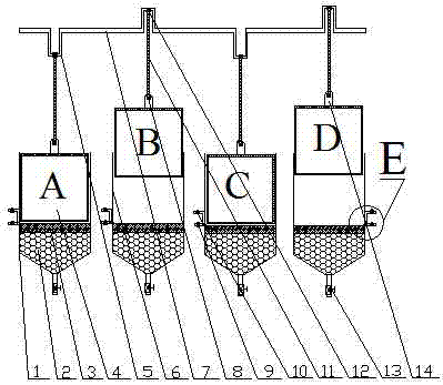
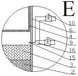
[0027] exist figure 1 In the embodiment shown in -2, the crankshaft drives the piston type molecular sieve oxygen generating system, which is composed of four sets of piston cylinder oxygen generating devices A, B, C, and D, and each set of piston cylinder oxygen generating devices includes piston 4, piston cylinder 6, Crankshaft 5, connecting rod 11, silo 1, oxygen exhaust valve 13, intake valve 9 and nitrogen exhaust valve 10; it is characterized in that: a piston cylinder 6 matching with piston cylinder 6 is installed in each set of piston cylinder oxygen making device The piston 4, the lower end of the piston cylinder 6 is the feed bin 1, the upper layer of the feed bin 1 is the filter layer 3, the lower layer of the feed bin 1 is the oxygen-producing molecular sieve 2, the funnel-shaped bottom of the feed bin 1 is connected with the oxygen exhaust valve 13, and the exhaust The oxygen valve 13 is an electric regulating valve; there is a piston head 14 in the center of the ...


PUM


Abstract

Crankshaft driven piston type molecular sieve oxygen generation system consists of four sets of piston cylinder oxygen generation devices A, B, C and D, each piston cylinder oxygen generation device includes piston, piston cylinder, crankshaft, connecting rod, silo, oxygen exhaust valve , intake valve and nitrogen exhaust valve; it is characterized in that: a piston is installed in the piston cylinder of each set of piston cylinder oxygen generator, the lower end of the piston cylinder is a silo, the upper layer of the silo is a filter layer, and the lower layer of the silo is Oxygen molecular sieve, the funnel-shaped bottom of the silo is connected with the oxygen exhaust valve; there is a piston head in the center of the top plane of the piston, the upper end of the piston head is connected with the connecting rod by the connecting shaft of the piston head and the connecting rod, and the upper end of the connecting rod is connected with the crankshaft by The crankshaft is connected to the connecting shaft of the connecting rod, and the crankshaft is connected to the transmission shaft, so that when the crankshaft rotates around the transmission shaft, it drives the connecting rod to move up and down and makes the upper end of the connecting rod swing back and forth around the connecting shaft between the piston head and the connecting rod, so that the piston moves on the piston. The cylinder moves up and down, and the composition and structure of the four sets of piston cylinder oxygen generators A, B, C and D are exactly the same.

Description

technical field [0001] The invention relates to a crankshaft-driven piston type molecular sieve oxygen production system, which is suitable for occasions where the amount of oxygen production is relatively small, and belongs to the technical field of oxygen production. Background technique [0002] Modern commonly used oxygen production methods include: cryogenic method, molecular sieve pressure swing adsorption method, membrane method and Wei Boqing’s magnetic separation method. The most energy-saving oxygen production method here is Wei Boqing’s magnetic separation method, but the magnetic separation method cannot be industrialized yet. , while the cryogenic method and molecular sieve pressure swing adsorption method cannot achieve miniaturization and low energy consumption, membrane oxygen production can help miniaturization, but the cost and energy consumption still cannot be reduced; Oxygen generators for office and household use, low energy consumption, low noise, no n...

Claims


Application Information

Patent Timeline
Patent Type & Authority Applications(China)
IPC IPC(8): C01B13/02
CPCC01B13/0259C01B2210/0028C01B2210/0046
Inventor 魏伯卿
Owner 洲利实业(上海)有限公司
Why Eureka
Try Eureka