Gradient type concrete water pipe control system and control method

A control system and concrete technology, which is applied to household refrigeration devices, lighting and heating equipment, household appliances, etc., can solve the problems of inability to control concrete cooling and fine control, and achieve the effects of reducing cracking risk, cost reduction, and heat insulation temperature rise

Active Publication Date: 2017-08-04
CCCC WUHAN HARBOR ENG DESIGN & RES
View PDF6 Cites 6 Cited by
  • Summary
  • Abstract
  • Description
  • Claims
  • Application Information

AI Technical Summary

Problems solved by technology

[0004] The purpose of the present invention is to overcome the problem that in the prior art concrete cooling technology, the same circulating water pipe will pass through various regions of different temperatures in the concrete structure at the same time, resulting in th

Method used


Image

  • Gradient type concrete water pipe control system and control method
  • Gradient type concrete water pipe control system and control method
  • Gradient type concrete water pipe control system and control method

Examples


Embodiment 1

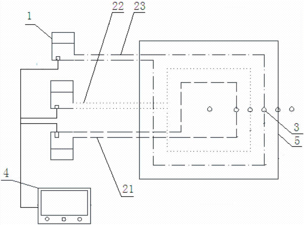
[0034] Embodiment 1: as figure 1 As shown, this embodiment provides a gradient concrete water pipe control system. In this embodiment, the distance range from the surface of the concrete structure to 50-80 cm inward is set as the low-temperature zone, and the temperature in this zone is usually 15°C~ lower than the high-temperature zone. 20°C; the area 100cm~200cm inward from the low temperature area is the medium temperature area, and the temperature in this area is 3°C~6°C lower than the temperature in the high temperature area; the high temperature area is inward from the medium temperature area. In this division, the high temperature area is usually The range is very large, and in the same high-temperature zone, there will also be a temperature difference of about 3°C;

[0035] The system includes,

[0036] The temperature sensor 3 is arranged in the concrete structure 5, and is used to detect the temperature of different positions of the concrete; the temperature sensor ...

Embodiment 2

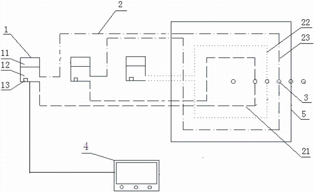
[0045] Embodiment 2: as figure 2 As shown, this embodiment also provides a gradient concrete water pipe control system, but the difference from Embodiment 1 is that in this embodiment, the outlet of the outer water control unit is connected to the water inlet end of the outer water pipe 23; The water return end of the outer water pipe 23 is connected to the inlet of the inner water control unit; the outlet of the inner water control unit is connected to the water inlet end of the inner water pipe 21; the return of the inner water pipe 21 The water end is connected to the inlet of the outer layer water control unit. That is, in this embodiment, the return water of the inner layer water pipe 21 will enter the outer layer water control unit, and because the temperature of the inner layer of concrete is higher, the water temperature of the water flowing back from the inner layer water pipe 21 will be higher than that of the inner layer The water inlet temperature of the water pi...

Embodiment 3

[0046] Embodiment 3: This embodiment also provides a gradient concrete water pipe control system, but the difference from Embodiment 1 is that in this embodiment, the temperature difference in different regions of the concrete during the heating process is first judged based on experience or experimental values. Then set multiple temperature zones according to the division method of a gradient every 5 degrees, and set a circulating water pipe 2 in each temperature zone. Multiple circulating water pipes 2 can be numbered in sequence according to the distance from the surface of the concrete structure, and each circulating water pipe 2 corresponds to a The circulating water control unit 3 and the control unit 4 independently control the water temperature of the circulating water pipe 2 in each temperature zone according to the temperature in the temperature zone. In some embodiments, the temperature zones of the concrete structure can also be divided according to other temperatur...


PUM


Abstract

The invention relates to the field of civil engineering, in particular to a gradient type concrete water pipe control system and control method. According to the gradient type concrete water pipe control system and control method, in the temperature rising period of concrete, the center temperature of the concrete can be reduced as quick as possible with the highest efficiency, the temperature can be reduced by 20-25 DEG C at maximum, adiabatic temperature rising of the concrete is equivalently reduced, and the cracking risk is reduced; in the temperature decreasing period of the concrete, the temperature decreasing speed of the concrete can be reduced by adjusting the water temperatures of water pipes in different positions of the concrete, the temperature decreasing speed of the concrete is smaller than or equal to 3.0 DEG/day, impact of contraction deformation is reduced, and the cracking risk is reduced; and meanwhile the concrete water pipe control system can automatically read the temperatures of temperature measuring points inside the concrete and adjust the water inlet temperatures of the water pipes according to the actual temperatures of the parts inside the concrete, the temperature gradient among the interior, middle and exterior of the concrete and air is reduced to the maximum extent, and the cracking risk is reduced.

Description

technical field [0001] The invention relates to the field of civil engineering, in particular to a gradient concrete water pipe control system and control method. Background technique [0002] Concrete cracks are a common phenomenon in concrete structures; the main reason for concrete cracks is that after concrete pouring, a large amount of hydration heat generated during the hydration of large-volume concrete cannot be dissipated, resulting in a temperature gradient between the outer layer of concrete and the interior of the concrete , resulting in temperature stress and cracks; in addition, after the concrete is poured, the water on the concrete surface evaporates too quickly, resulting in a large negative pressure in the capillary and a sharp shrinkage of the concrete volume. At this time, the concrete has low strength and cannot resist this deformation stress. And lead to cracking; the existence of such cracks will not only affect the life of the building and the appeara...

Claims


Application Information

Patent Timeline
IPC IPC(8): E04G21/24F25D31/00F25D29/00
CPCE04G21/24F25D29/001F25D31/00
Inventor 刘可心汪华文吴珂余文志岳新兴刘苗李寒
Owner CCCC WUHAN HARBOR ENG DESIGN & RES
Why Eureka
Try Eureka