Hydrogen liquefying device and method

A hydrogen and nitrogen technology, applied in liquefaction, refrigeration, liquefaction, solidification, etc., can solve problems such as difficult maintenance and complicated process, and achieve the effect of easy maintenance, simple process and strong operability

Active Publication Date: 2017-08-04
四川蜀道装备科技股份有限公司
View PDF5 Cites 13 Cited by
  • Summary
  • Abstract
  • Description
  • Claims
  • Application Information

AI Technical Summary

Problems solved by technology

The existing hydrogen liquefaction cycle device and method with an expander have complicated pr

Method used


Image

  • Hydrogen liquefying device and method
  • Hydrogen liquefying device and method

Examples


Embodiment 1

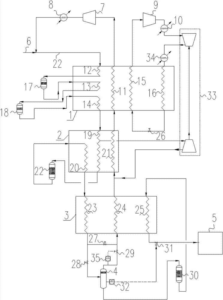
[0032] Such as figure 1 As shown, a device for hydrogen liquefaction, which includes a hydrogen inlet pipeline 6, a heat exchanger A1, a heat exchanger B2, a heat exchanger C3, a flash tank 4 and a liquid hydrogen storage tank 5 connected in sequence, and the heat exchanger Air intake channel A and return channel A11 are provided in A1, intake channel B and return channel B21 are provided in heat exchanger B2, subcooling channel C23 and return channel C are provided in heat exchanger C3, and hydrogen enters Air pipe 6 communicates with the air inlet of air intake channel A, the air outlet of air intake channel communicates with the air inlet of air intake channel B, the air outlet of air intake channel B communicates with the air inlet of supercooling channel C23, and the air outlet of overcooling channel C23 communicates. The gas outlet of the cold channel C23 is connected with the air inlet of the flash tank 4, the liquid outlet of the flash tank 4 is connected with the liqu...

Embodiment 2

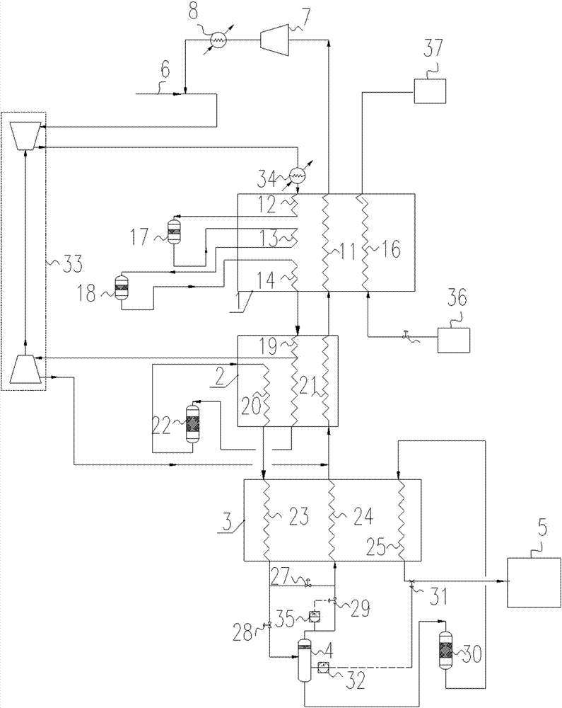
[0044] Such as figure 2 As shown, the difference between the present embodiment and the device in Embodiment 1 is that the hydrogen inlet pipeline 6 communicates with the first pre-cooling passage A12 through the pressurized end of the turbocharger expander 33, and the first pre-cooling passage A12 communicates with the turbocharging end of the turbocharger expander 33. A turbocharged expander cooler 34 is provided between the pressurized ends of the flat booster expander 33, a nitrogen channel 16 is provided in the heat exchanger A1, the inlet of the nitrogen channel 16 is provided with external liquid nitrogen, and the nitrogen channel 16 The outlet is equipped with a nitrogen storage device. By setting the external liquid nitrogen instead of the closed nitrogen refrigeration cycle, the composition of the device is reduced, and the turbocharger expander 33 is used to pressurize the hydrogen before the precooling channel A.


PUM


Abstract

The invention discloses a hydrogen liquefying device. The hydrogen liquefying device comprises a hydrogen intake pipe, a heat exchanger A, a heat exchanger B, a heat exchanger C, a flash tank and a liquid hydrogen storage tank for communicating in sequence. The invention further discloses a hydrogen liquefying method, comprising the following steps: (S1) hydrogen is precooled; (S2) orthohydrogen and parahydrogen are converted and liquefied; (S3) one part of liquid hydrogen serves as supercooled gas to input back into the heat exchanger C; (S4) hydrogen steam and the liquid hydrogen are separated by the flash tank; and the liquid hydrogen is prepared and stored; and (S5) unliquefied hydrogen is recovered. The hydrogen liquefying method is simple in flow, flexible in adjustment, reliable in work, convenient to maintain and low in energy consumption.

Description

technical field [0001] The invention relates to hydrogen liquefaction, in particular to a hydrogen liquefaction device and method. Background technique [0002] Hydrogen is the main industrial raw material, and also the most important industrial gas and special gas. It has been widely used in petrochemical industry, electronics industry, metallurgical industry, food processing, float glass, fine organic synthesis, aerospace and other fields. On the other hand, hydrogen is also an important energy source. The calorific value of hydrogen is relatively high, which is about three times the calorific value of gasoline. The combustion of hydrogen is relatively good, and it is flammable in the range of 3% to 97%. Hydrogen has good recyclability, and the water generated by the combustion reaction can be recycled and re-produced. It is the fuel for future power generation and fuel cells for electric vehicles. It is foreseeable that the future world will transform from a carbon-based...

Claims


Application Information

Patent Timeline
IPC IPC(8): F25J1/02
CPCF25J1/0219F25J1/0279F25J2215/10F25J1/001F25J1/0037F25J1/004F25J1/0052F25J1/0072F25J1/0208F25J1/0224F25J1/0285F25J1/0288F25J2210/42F25J2230/20F25J2290/34
Inventor 马忠文向南陈田田
Owner 四川蜀道装备科技股份有限公司
Why Eureka
Try Eureka