

Multifunctional pressure oscillation tube test platform with two open ends
A test platform and oscillating tube technology, which is applied in the field of multi-functional open-ended pressure oscillating tube testing platforms, can solve the problems of large influence on the performance of the air wave machine, different working processes, and long research period, so as to reduce the research cost and improve the The effect of research efficiency
- Summary
- Abstract
- Description
- Claims
- Application Information
AI Technical Summary
Problems solved by technology
Method used
Image

Examples
Embodiment Construction
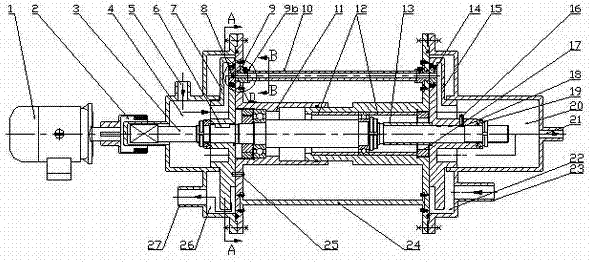
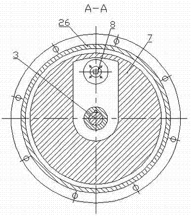
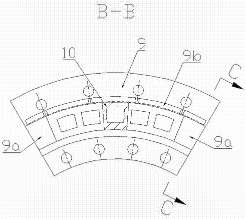
[0021] figure 1 , 2 A structural diagram of a test platform for a multifunctional pressure oscillation tube with openings at both ends is shown. In the figure, this multi-function pressure oscillation tube test platform with both ends openings includes a housing, a motor 1, a magnetic coupling 2, a central shaft 3, a left cavity turntable 7, a right cavity turntable 15, and a pressure oscillation tube with both ends openings. 10. The casing includes a cylinder 11, a left end high pressure air intake chamber 4 with a high pressure air inlet 5, a left end low temperature exhaust chamber 26 and a low temperature air outlet 27, and a left end high pressure air inlet chamber 4 with a high temperature air outlet 21 and a right end medium pressure air inlet chamber. 22 and the right end high-temperature exhaust cavity 20 of the medium pressure air inlet 23. A labyrinth sealing structure is adopted between the left end high-pressure air intake cavity body 4 and the left cavity turn...
PUM
 Abstract
Description
Claims
Application Information