Three-coordinate low-altitude small target radar

A small target, three-coordinate technology, applied in the field of radar systems, can solve the problems of inability to accurately monitor the height of low-altitude areas, inflexible beam pointing, and slow speed, and achieve the effect of excellent technical indicators, light weight, and slow speed

Active Publication Date: 2017-08-04
ANHUI SUN CREATE ELECTRONICS
View PDF6 Cites 17 Cited by
  • Summary
  • Abstract
  • Description
  • Claims
  • Application Information

AI Technical Summary

Problems solved by technology

[0003] The beam scanning of ordinary radar is to realize the mechanical scanning by the rotation of the radar antenna. The beam pointing in this way is not flexible, and it is impossible to accurately monitor the low-altitude, slow-speed, and small-sized targets in the low-altitude area.

Method used


Image

  • Three-coordinate low-altitude small target radar
  • Three-coordinate low-altitude small target radar
  • Three-coordinate low-altitude small target radar

Examples


Embodiment Construction

[0049] The technical solutions in the embodiments of the present invention will be clearly and completely described below with reference to the accompanying drawings in the embodiments of the present invention. Obviously, the described embodiments are only a part of the embodiments of the present invention, but not all of the embodiments. Based on the embodiments of the present invention, all other embodiments obtained by those of ordinary skill in the art without creative efforts shall fall within the protection scope of the present invention.

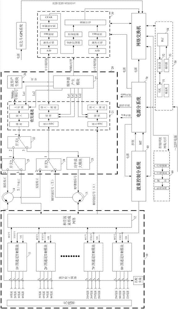
[0050] like figure 1 As shown, a three-coordinate low-altitude small target radar includes an antenna feeder sub-system 10, a receiving sub-system 20, a signal processing sub-system 30, a beam control sub-system 40, a turntable servo sub-system 50, a terminal sub-system 60 and a power sub-system 70 ; The data information between each system is transmitted through the network switch, and the low altitude refers to the target below 3 ki...


PUM


Abstract

The invention relates to a radar system, specifically to a three-coordinate low-altitude small target radar. The three-coordinate low-altitude small target radar comprises an antenna feeder subsystem, a receiving subsystem, a signal processing subsystem, a wave beam control subsystem, a rotary table servo subsystem, a terminal subsystem and a power supply subsystem, a four-channel T / R module adopts a distributed T / R component, and the component adopts highly integrated design and has the advantages of light weight, small size, good consistency, excellent technical indexes and the like. The three-coordinate low-altitude small target radar provided by the invention can realize search and tracking of an aerodynamic target such as a small airplane, a paraglider and an unmanned aerial vehicle in a low-altitude airspace in a range with a central radius of 45km, precisely monitor the target in the low-altitude area which is low in height, slow in speed and small in size, display and output distance, direction, speed and height information of the flight target, and form a three-coordinate motion situation of the low-altitude target.

Description

technical field [0001] The invention relates to a radar system, in particular to a three-coordinate low-altitude small target radar. Background technique [0002] Phased array radar is a phase-controlled electronically scanned array radar. It uses a large number of individually controlled small antenna elements to form an antenna array. Each antenna element is controlled by an independent switch. Based on the Huygens principle, it controls the time difference of each antenna element's emission. , the main beams of different phases (directions) can be synthesized, and the phase changes can be performed in both axes; similar to Thomas Young's double-slit experiment, the electromagnetic waves emitted by each phase shifter of the phased array interfere constructively The principle strengthens and synthesizes a nearly straight radar main lobe, while the side lobes are greatly reduced due to interference cancellation. [0003] The beam scanning of ordinary radars relies on the ro...

Claims


Application Information

Patent Timeline
Patent Type & Authority Applications(China)
IPC IPC(8): G01S13/02G01S13/66G01S7/40
CPCG01S7/4004G01S13/02G01S13/66
Inventor 吴俊任翔徐鹏来陈龙杨琳陈娟陶少杰徐明飞
Owner ANHUI SUN CREATE ELECTRONICS
Why Eureka
Try Eureka