

Dual-robot cooperation welding and detection apparatus control system
A detection device and dual-robot technology, applied in the general control system, control/regulation system, program control, etc., can solve the problems of low equipment utilization, high labor cost, high work intensity, etc., and achieve high welding quality consistency, The effect of high degree of automation and high welding precision
- Summary
- Abstract
- Description
- Claims
- Application Information
AI Technical Summary
Problems solved by technology
Method used
Image

Examples
Embodiment Construction
[0048] The present invention will be further described below in conjunction with drawings and embodiments.
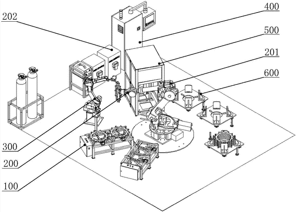
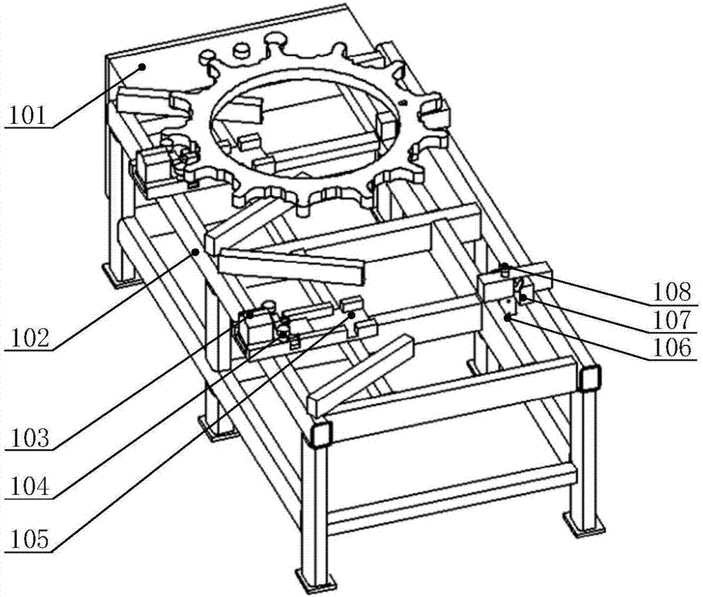
[0049] as attached figure 1 As shown, the embodiment of the present invention comprises four fixed feed bins 100, a handling robot mechanism 200, an intelligent control system 400, a welding robot mechanism 300, a visual detection device 500 and two mobile feed bins 600; four fixed feed bins 100, The two mobile bins 600 , the welding robot mechanism 300 and the visual inspection device 500 are all placed around the transfer robot mechanism 200 . The fixed bins 100 are arranged at the loading station, and each fixed bin 100 has a clamping cylinder and a positioning cylinder, so there are four clamping cylinders and positioning cylinders. The welding robot mechanism 300 is placed at the welding station, the visual inspection device 500 is arranged at the inspection station, the mobile bin 600 is arranged at the blanking station, and the intelligent control system 400 is ...
PUM
 Abstract
Description
Claims
Application Information