Smelting device and alloy smelting method

A technology of alloy and crucible, which is applied in the field of smelting and smelting equipment, can solve the problems of easy inclusion of gas, poor heating effect, affecting the composition consistency of alloy products, etc., and achieve the effect of simple smelting equipment

Pending Publication Date: 2017-08-08
宋佳
View PDF5 Cites 6 Cited by
  • Summary
  • Abstract
  • Description
  • Claims
  • Application Information

AI Technical Summary

Problems solved by technology

In the extensive smelting process or the production process of master alloys with low requirements, the above-mentioned smelting and pouring process can still be used for mass production. However, as various casting methods have higher and higher requirements for the metal smelting process, The crucible melting method in the prior art has been difficult to meet the requirements
[0003] The main disadvantages of crucible smelting and dumping are as follows: (1) The alloy melt is prone to splash during pouring, resulting in material loss; (2) Since the heating has been stopped, the heat loss during pouring may cause The segregation of some components in the alloy melt, and the easy inclusion of gas in it, increases the porosity of the product after solidification; (3) The kinetic energy of the alloy melt during the pouring process is relatively large, and the cooling time interval in the subsequent process container is long. It is easy to stratify after solidification; (4) Affected by the turning angle of the crucible, the inside of the melting crucible is prone to residue, which affects the life of the crucible, and also affects the composition consistency of the next batch of smelted alloy products
In the above technical solution, although the problems caused by dumping the crucible are improved, since the conventional heating method often adopts resistance heating or induction heating, the bottom of the crucible is a part with poor heating effect. Second, in order to obtain a uniform melting effect, the blanking The hole sealing and control structure are uniformly placed in the heating source, so that the closed structure of the blanking hole formed in this way is easy to fail in high temperature environment, resulting in the situation that the solution cannot flow out or leaks

Method used


Image

  • Smelting device and alloy smelting method
  • Smelting device and alloy smelting method
  • Smelting device and alloy smelting method

Examples


Embodiment 2

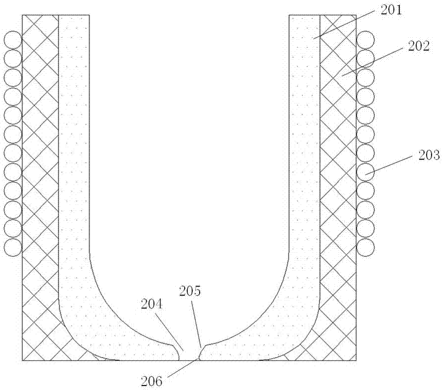
[0033] The structure of embodiment 2 is as attached figure 2 As shown, a thermal insulation layer 202 is provided outside the crucible 201, and a cooling circulating water component (not shown) is provided on the side near the crucible inside the thermal insulation layer. The thermal insulation layer can effectively ensure that the heat will not be lost during the melting process and improve the melting efficiency. The addition of cooling circulating water components can effectively control the temperature of the crucible.

Embodiment 3

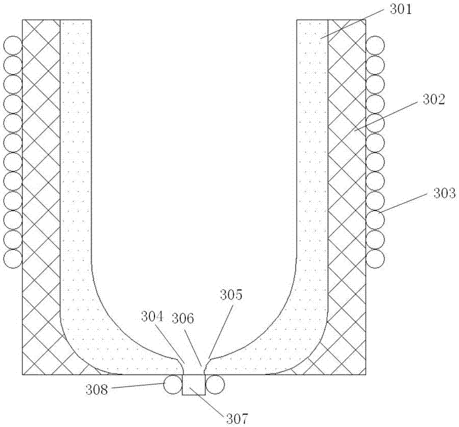
[0034] The structure of embodiment 3 is as attached image 3 As shown, the bottom of the crucible blanking hole 304 is provided with a drainage channel 307 connected thereto, and a heat preservation induction coil 308 is provided outside the drainage channel. The smelting device in the present invention may need to change the height or direction of the blanking in the process of cooperating with other casting devices. Adding a drainage channel can meet this requirement, and adding induction coils on both sides of the drainage channel can prevent the alloy melt from melting. Freezes when poured out. In the smelting process, the molten alloy melt flows from the blanking hole through the drain to the subsequent process container.

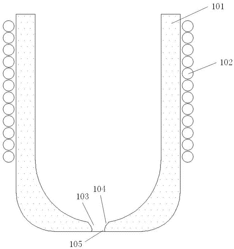
[0035] Furthermore, in order to make the molten alloy flow out smoothly, the end of the crucible’s blanking hole and the side wall of the crucible are in an arc transition, and the blanking hole is set at the center of the bottom of the crucible, as s...


PUM


Abstract

The invention discloses a smelting device. The smelting device comprises a crucible body. The smelting device is characterized in that a through hole used as a discharging hole is formed in the bottom part of a crucible, wherein a smelting sensing coil is arranged at the outside of the crucible, and the working length of the smelting sensing coil is not greater than the height of the crucible; the smelting sensing coiling is provided with a driving assembly in a connecting manner and is driven by the driving assembly to move opposite to the crucible in the axial direction of the crucible. With the adoption of the smelting device and the smelting device, the shortages caused by a discharging technology of toppling over the crucible in the prior art can be avoided; alloy raw material can be uniformly smelted; and moreover, the device and the method are convenient and reliable, applicable to various alloy smelting applies, and particularly applicable to a smelting alloy smelting technology with high requirement.

Description

technical field [0001] The invention belongs to the field of metal materials, and in particular relates to a smelting device and a smelting method using the device. Background technique [0002] The melting and refining process is one of the casting production processes of metal materials. It is to put metal materials and other auxiliary materials into the heating furnace for melting and tempering. The raw material melt undergoes certain physical and chemical changes in the high-temperature furnace to produce crude metal or Pyrometallurgical processes of metal concentrates and slags. The smelting utensils used in the process of alloy smelting are often crucibles. In the smelting process, the alloy raw materials are heated and melted to form a uniform melt, and then the crucible is turned over to pour the melt into a container in the subsequent process, such as pouring into a die-casting mold for subsequent processing. As a smelting tool, crucibles have been widely used in ...

Claims


Application Information

Patent Timeline
Patent Type & Authority Applications(China)
IPC IPC(8): F27B14/14F27B14/06F27B14/18C22C1/02
CPCF27B14/061F27B14/0806F27B14/14C22C1/02F27B2014/0818Y02P10/25
Inventor 宋佳
Owner 宋佳
Why Eureka
Try Eureka