Correction method and correction device of magnetic resonance system

A correction method and magnetic resonance technology, which is applied in the direction of using nuclear magnetic resonance imaging system for measurement, magnetic resonance measurement, and magnetic variable measurement, can solve the problems of influence and accuracy that need to be further improved, so as to achieve accurate measurement results and avoid detection effect of error

Active Publication Date: 2017-08-08
SHANGHAI UNITED IMAGING HEALTHCARE
View PDF9 Cites 25 Cited by
  • Summary
  • Abstract
  • Description
  • Claims
  • Application Information

AI Technical Summary

Problems solved by technology

However, the accuracy of the signal collected by this method is easily affected by unideal factors. For example, in the case of uneven B0 field, the results of the GRE sequence and SE sequence will be greatly affected; the sampling interval of the ADC when collecting data It is not infinitely small. By calculating the position of the maximum value, the accuracy can only be controlled at the level of the sampling interval, and the accuracy needs to be further improved.

Method used


Image

  • Correction method and correction device of magnetic resonance system
  • Correction method and correction device of magnetic resonance system
  • Correction method and correction device of magnetic resonance system

Examples


Embodiment Construction

[0037] In order to make the above objects, features and advantages of the present invention more obvious and comprehensible, specific implementations of the present invention will be described in detail below in conjunction with the accompanying drawings and embodiments.

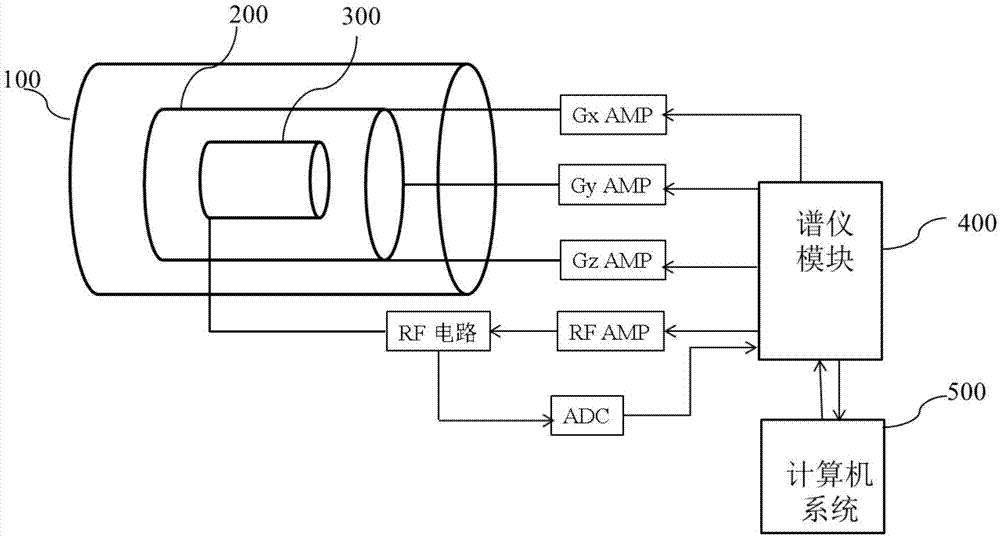
[0038] Such as figure 1As shown, the magnetic resonance system hardware mainly includes: a magnet module 100, a gradient module 200, a radio frequency module 300, a spectrometer system 400, a computer system 500 and other auxiliary systems, wherein the magnet module 100 is used to generate the main magnetic field, and the gradient module 200 is mainly Including gradient current amplifier (AMP), gradient coil; RF module 300 mainly includes RF transmitting module and RF receiving module; spectrometer system 400 mainly includes pulse sequence generator, gradient waveform generator, transmitter and receiver etc., and computer system 500 is used to control the operation of the system and the final imaging. The ge...


PUM


Abstract

The invention discloses a correction method of a magnetic resonance system. The magnetic resonance system comprises an RF transmitting module, a gradient module and an RF receiving module. The correction method comprises the steps of executing a first pulse sequence, acquiring a first set of echo signals and acquiring a frequency domain phase of the first set of echo signals, wherein the first pulse sequence is a spin echo sequence; executing a second pulse sequence, acquiring a second set of echo signals and acquiring the frequency domain phase of the second set of the echo signals, wherein the second pulse sequence is a non-selective layer spin echo sequence; acquiring a system relative time delay according to the frequency domain phases of the first set of echo signals and the second set of echo signals, wherein the system relative time delay comprises a relative time delay between the RF transmitting module and the gradient module and a relative time delay between the RF receiving module and the gradient module; and performing compensation on the magnetic resonance system according to the system relative time delay. According to the correction method and the correction device, the relative time delay of the magnetic resonance system can be accurately acquired through phase operation on the echo signal. Furthermore the invention provides a correction device of the magnetic resonance system.

Description

[0001] 【Technical field】 [0002] The invention relates to the technical field of magnetic resonance imaging, in particular to a correction method and device for a magnetic resonance system. [0003] 【Background technique】 [0004] Magnetic Resonance Imaging (MRI) is a new type of medical imaging technology that mainly uses the nuclear magnetic resonance phenomenon of a certain nucleus in human tissue, and processes the radio frequency signal obtained by a computer to reconstruct an image of a certain level of the human body. Due to its non-ionizing radiation, multi-sequence, multi-parameter, multi-plane imaging and high soft tissue resolution, it is widely used in the diagnosis of diseases. MRI signal intensity is usually affected by various factors such as tissue proton density, T1 value, and T2 value. Imaging quality can be improved by adjusting imaging parameters such as radiofrequency pulse, gradient field, and signal acquisition time. Usually, the setting of relevant par...

Claims


Application Information

Patent Timeline
Patent Type & Authority Applications(China)
IPC IPC(8): G01R33/54
CPCG01R33/54
Inventor 李博
Owner SHANGHAI UNITED IMAGING HEALTHCARE
Why Eureka
Try Eureka