
Cage type rotor shaft radial mixed magnetic flux multi-disc type permanent magnet motor

A squirrel-cage rotor, permanent magnet motor technology, applied to synchronous motors with stationary armatures and rotating magnets, asynchronous induction motors, and magnetic circuit shapes/styles/structures, etc. Unstable starting process, low starting torque, etc., to achieve the effect of facilitating processing and later operation and maintenance, widening the speed regulation range, and compact motor structure

Active Publication Date: 2017-08-08
HUAZHONG UNIV OF SCI & TECH
View PDF8 Cites 10 Cited by
  • Summary
  • Abstract
  • Description
  • Claims
  • Application Information

AI Technical Summary

Problems solved by technology

[0005] Aiming at the defects of the prior art, the object of the present invention is to provide a cage-type rotor shaft-radial mixed flux multi-disk permanent magnet motor, which aims to solve the problem of low starting torque of the existing shaft-radial hybrid flux permanent magnet motor. The starting process is not stable, and the technical problems of low-speed and high-speed running performance cannot be considered

Method used


Image

  • Cage type rotor shaft radial mixed magnetic flux multi-disc type permanent magnet motor
  • Cage type rotor shaft radial mixed magnetic flux multi-disc type permanent magnet motor
  • Cage type rotor shaft radial mixed magnetic flux multi-disc type permanent magnet motor

Examples


Embodiment Construction

[0029] In order to make the object, technical solution and advantages of the present invention clearer, the present invention will be further described in detail below in conjunction with the accompanying drawings and embodiments. It should be understood that the specific embodiments described here are only used to explain the present invention, not to limit the present invention.

[0030] The invention provides a permanent magnet motor that can not only improve the space utilization rate of the motor, but also improve the torque quality, torque density and system efficiency, and can take into account both low-speed and high-speed operation performance. The motor can be used for high-end CNC machine tool electric spindles , robot joints, electric vehicle hub drives, etc.

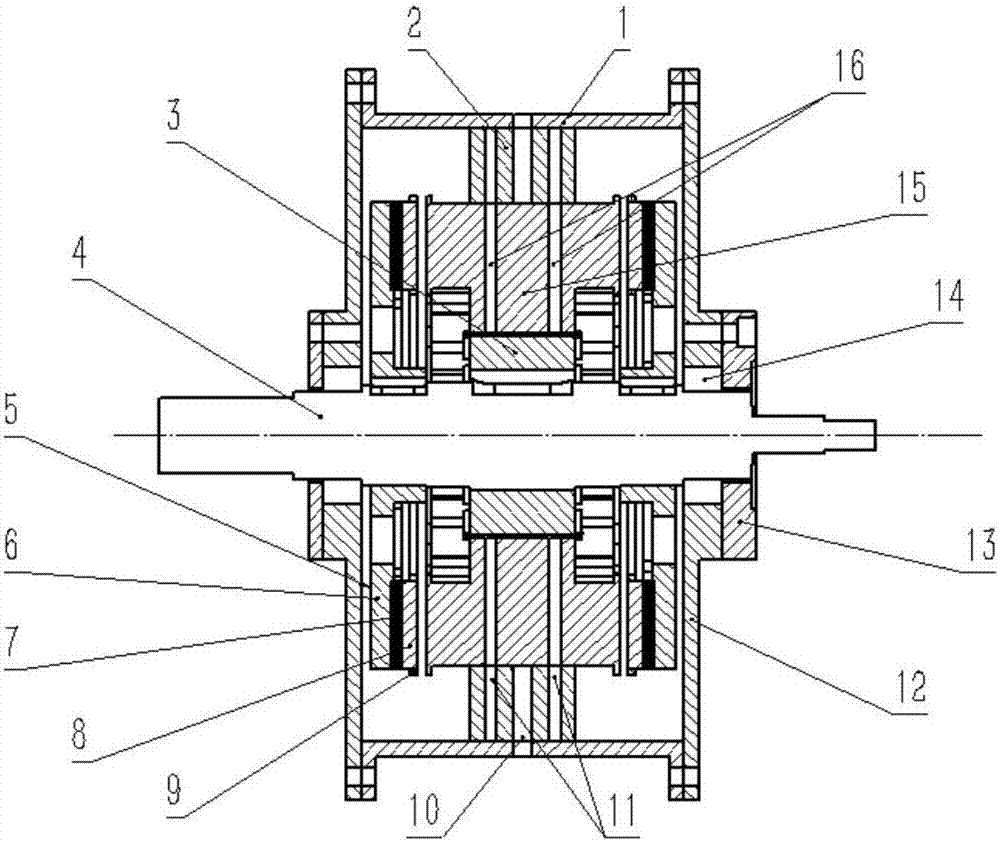
[0031] Such as figure 1 As shown, the present invention provides a cage-type rotor shaft radial mixed flux multi-disk permanent magnet motor, including a stator, a rotor, and a motor casing composed of a ro...


PUM


Abstract

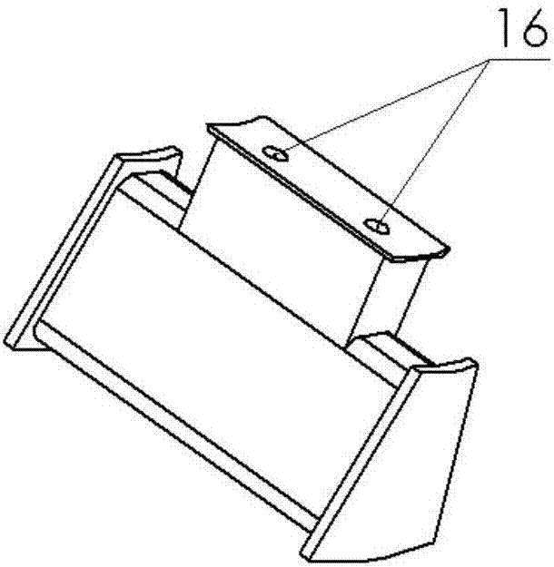
The invention discloses a cage type rotor shaft radial mixed magnetic flux multi-disc type permanent magnet motor. The permanent magnet motor comprises a motor shell, a motor rotor and a motor stator, wherein the motor shell consists of a rotary shaft, bearings, end covers, pressing covers and a machine shell jointly; the motor rotor consists of two coaxially-fixed outer rotors and a salient pole rotor in the middle jointly; the motor stator consists of a plurality of modular T-shaped stator iron cores in circumferential distribution, a winding and an aluminum ring; the two outer rotors comprise outer rotor yoke parts, permanent magnets, cage grooves and cage rings separately; the permanent magnets are arranged in a combined type bidirectional inclined pole structure; the stator iron cores and the aluminum ring are both concentric with the salient pole rotor; and the rotary shaft, the salient pole rotor, the stator iron cores, the aluminum ring and the machine shell are arranged in sequence from the rotary shaft to the machine shell. By virtue of the cage type rotor shaft radial mixed magnetic flux multi-disc type permanent magnet motor, the slot space-factor, the winding end part utilization rate, the torque quality, the torque and power density, the low-speed and high-speed operating performance of the motor, and the overall operating efficiency of the motor can be improved.

Description

technical field [0001] The invention belongs to the technical field of motors, and more specifically relates to a cage-type rotor shaft-radial hybrid flux multi-disk permanent magnet motor. Background technique [0002] At present, the commonly used permanent magnet motors are generally divided into two types: radial flux and axial flux permanent magnet motors. However, the utilization rate of the ends is low, the overall space utilization rate of the motor is not high, and the performance of low-speed and high-speed operation cannot be balanced. There is still room for improvement in motor torque density and power density. [0003] In traditional motor design, the size of the motor is optimized. For example, the radial permanent magnet motor adopts a structure with a large aspect ratio, and the axial permanent magnet motor adopts a structure with a small aspect ratio; technologies such as fractional concentrated windings are used to improve Torque density, but its effect i...

Claims


Application Information

Patent Timeline
IPC IPC(8): H02K17/18H02K21/24H02K1/14H02K1/20H02K1/24H02K1/27H02K3/18
CPCH02K1/148H02K1/20H02K1/24H02K1/2793H02K3/18H02K21/24H02K17/18Y02T10/64
Inventor 杨凯孙宋君吴冇
Owner HUAZHONG UNIV OF SCI & TECH
Learn More