
Feedback control circuit and output signal control method for optoelectronic detection apparatus

A feedback control, photoelectric detection technology, applied in electromagnetic wave transmission systems, electrical components, transmission systems, etc., can solve problems such as output signal stability and crossover

Inactive Publication Date: 2017-08-08
ZTE CORP
View PDF4 Cites 1 Cited by
  • Summary
  • Abstract
  • Description
  • Claims
  • Application Information

AI Technical Summary

Problems solved by technology

[0005] In order to solve the above technical problems, the present invention provides a feedback control circuit and an output signal control method of a photodetector device to solve the It has a great influence on the output electrical signal, which leads to the problem of cross stability of the output signal of the photoelectric detection device

Method used


Image

  • Feedback control circuit and output signal control method for optoelectronic detection apparatus
  • Feedback control circuit and output signal control method for optoelectronic detection apparatus
  • Feedback control circuit and output signal control method for optoelectronic detection apparatus

Examples


Embodiment Construction

[0042] In order to make the purpose, technical solution and advantages of the present invention more clear, the embodiments of the present invention will be described in detail below in conjunction with the accompanying drawings. It should be noted that, in the case of no conflict, the embodiments in the present application and the features in the embodiments can be combined arbitrarily with each other.

[0043] The steps shown in the flowcharts of the figures may be performed in a computer system, such as a set of computer-executable instructions. Also, although a logical order is shown in the flowcharts, in some cases the steps shown or described may be performed in an order different from that shown or described herein.

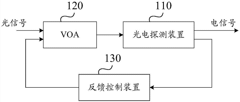
[0044] figure 1 A schematic structural diagram of a feedback control circuit provided by an embodiment of the present invention. The feedback control circuit method provided in this embodiment is suitable for controlling the output signal of the photoele...


PUM


Abstract

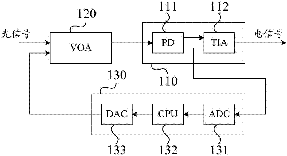
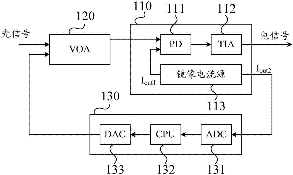
The invention discloses a feedback control circuit and an output signal control method for an optoelectronic detection apparatus. The feedback control circuit provided by the invention comprises an optoelectronic detection apparatus, a variable optical attenuator (VOA) and a feedback control apparatus, wherein the VOA is connected to an input end of the optoelectronic detection apparatus and is used for performing energy attenuation on an input optical signal and transmitting the attenuated optical signal to the optoelectronic detection apparatus; the feedback control apparatus is connected to an output end of the optoelectronic detection apparatus, an output end of the feedback control apparatus is connected to an input end of the VOA, and the feedback control apparatus is used for generating a first control signal according to an electrical signal output by the optoelectronic detection apparatus, and transmitting the first control signal to the VOA. The invention solves a problem of poor stability of the output signal of the optoelectronic detection apparatus, which is caused by a great influence of change of strength of the input optical signal on the output electrical signal in a process of adopting the optoelectronic detection apparatus to convert the optical signal into the electrical signal.

Description

technical field [0001] The invention relates to the technical field of optical fiber communication, in particular to a feedback control circuit and an output signal control method of a photoelectric detection device. Background technique [0002] With the development of optical fiber communication technology, compared with the traditional coaxial twisted pair, the use of optical fiber as a transmission medium in communication equipment has large transmission capacity, long transmission distance, low transmission loss, and strong anti-radiation and anti-interference ability. And it is easier to realize the advantages of highly integrated and intelligent networking equipment. [0003] The current optical fiber communication market is developing rapidly, and its business scope is gradually expanding. For example, network communications such as telecommunications have adopted optical fiber transmission to replace traditional coaxial twisted pair wires. The market profits and mar...

Claims


Application Information

Patent Timeline
IPC IPC(8): H04B10/69H04B10/073
CPCH04B10/69
Inventor 杨俊王滔余涛
Owner ZTE CORP
Learn More