Cutting method for glass laminate

A technology of glass layers and laminates, applied in glass cutting devices, glass/slag layered products, glass manufacturing equipment, etc., can solve the problems of easy bending and low rigidity, and achieve the effect of reducing cutting residues

Inactive Publication Date: 2017-08-11
ASAHI GLASS CO LTD
View PDF2 Cites 2 Cited by
  • Summary
  • Abstract
  • Description
  • Claims
  • Application Information

AI Technical Summary

Problems solved by technology

[0004] However, since such a composite is obtained by forming a resin film on a very thin glass plate, its rigidity is low, and it tends to bend easily due to its own weight.

Method used


Image

  • Cutting method for glass laminate
  • Cutting method for glass laminate
  • Cutting method for glass laminate

Examples


Embodiment 1

[0210] Here, examples and comparative examples obtained by changing cutting conditions will be described.

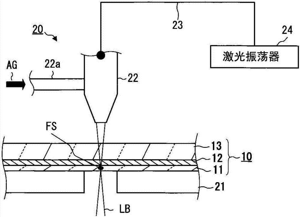
[0211] Laser light LB is vertically incident on the glass laminated body 10 from the support glass 13 side from directly above. At this time, the pulse energy density is set to 14.1J / mm 2 , Overlap rate is set to 25%. Here, the pulse energy density refers to a value obtained by dividing the pulse average energy of the laser beam LB by the pulse area. The overlapping ratio L is expressed by the following formula 4, and the schematic diagram is as follows Figure 5 shown.

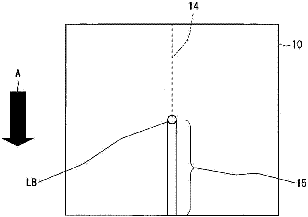
[0212] D0 represents the focusing diameter (mm) of the pulse of the laser beam LB, v represents the cutting speed (mm / s), and f represents the oscillation frequency (Hz) of the laser beam LB. After the pulsed spot SP1 is formed, the next spot SP2 is formed at a position moved away from SP1 by the moving distance v / f [mm].

[0213] L=(D0-v / f) / D0×100···Formula (4)

[0214] Tables 1 and 2 show exampl...

Embodiment 2~4

[0232] In Examples 2 to 4, the pulse energy density and overlap ratio in Example 1 were changed to the values ​​shown in the table, and the other conditions were the same as in Example 1.


PUM

PropertyMeasurementUnit
thicknessaaaaaaaaaa
thicknessaaaaaaaaaa
thicknessaaaaaaaaaa

Abstract

There is provided a method for cutting a glass laminate which has been reduced in the thickness of the resin layer. Wherein the glass laminate is laminated with a first glass plate and a second glass plate thinner than the first glass plate with a resin layer interposed therebetween, and the cutting method has a method of cutting off the glass (A) and (B): F >= 3 (A), and the pulse energy density F [J / mm2] and the overlap ratio [%] L of the laser light, 0.09L + 11.8 Formula (B). Here, L = (D0-V / f) / D0100, D0 represents the condensed diameter (mm) of the pulse of the laser light, v represents the cutting speed (mm / s), f represents the oscillation frequency of the laser Hz).

Description

technical field [0001] The present invention relates to a cutting method of a glass laminate. Background technique [0002] Conventionally, glass plates have been used as substrates for organic EL displays / panels, and recently, substrates using resin plates such as polyimide have begun to be produced. A resin plate is more flexible than a glass plate, and it is easy to manufacture a curved organic EL display / panel. Such organic EL panels are used in smartphones, televisions, and the like with curved display surfaces. [0003] On the other hand, since the resin plate is inferior to the glass plate in gas barrier properties, there is a problem that moisture and oxygen permeate from the outside air, deteriorating the element. Therefore, in order to solve such a problem, studies have been made to use a composite obtained by forming a resin film on an ultra-thin glass plate for an organic EL panel. For example, Patent Document 1 discloses a composite comprising a cage silsesqu...

Claims


Application Information

Patent Timeline
Patent Type & Authority Applications(China)
IPC IPC(8): B23K26/38B32B38/00
CPCB23K26/38B32B38/0004B28D5/04B32B17/10036B32B27/281C03B33/078C03B33/082C03B33/091
Inventor 清水隆夫后藤真毅木村昭太角田纯一
Owner ASAHI GLASS CO LTD
Why Eureka
Try Eureka