
Assembly structure and assembly joint of steel pipe concrete combined truss

A technology of steel tube concrete and composite truss, which is applied in truss structures, truss beams, building structures, etc. It can solve the problems of low bearing capacity, small truss shear stiffness, failure of the whole truss, etc., and improve fire performance and durability , improve local stability and stiffness, and reduce the difficulty of transportation and loading and unloading

Pending Publication Date: 2017-08-11
FUJIAN UNIV OF TECH
View PDF5 Cites 1 Cited by
  • Summary
  • Abstract
  • Description
  • Claims
  • Application Information

AI Technical Summary

Problems solved by technology

Limited by on-site construction conditions, welding often needs to be completed in the factory, so the workload is heavy, the production cost is high, and the processing cycle is long. Low
For large-scale truss structures, due to the cross-section and self-heavy weight of the rods, the requirements for hoisting machinery are very high. A lot of welding work needs to be carried out before or during the hoisting on site, so welding is difficult and the quality is difficult to guarantee
[0003] When the traditional steel pipe truss is stressed, the failure mode of the member is mostly the buckling of the truss node or the cracking of the weld at the joint between the main limb and the pipe attachment. The shear stiffness of the truss is small, the bearing capacity is low, and the mechanical properties of the material have not been obtained. Full play; if the traditional steel pipe truss is corroded or partially damaged, its maintenance is difficult, costly and difficult to replace
At the same time, the fire resistance of the node area is poor, and once damaged, it is easy to cause the failure of the whole truss
[0004] For traditional steel pipe concrete trusses, steel pipe trusses are usually made first, and then concrete is poured on site, which is bound to be detrimental to energy conservation and environmental protection

Method used


Image

  • Assembly structure and assembly joint of steel pipe concrete combined truss
  • Assembly structure and assembly joint of steel pipe concrete combined truss
  • Assembly structure and assembly joint of steel pipe concrete combined truss

Examples


Embodiment 1

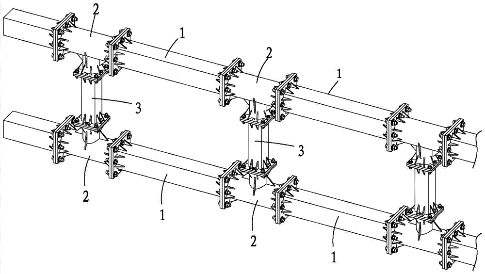
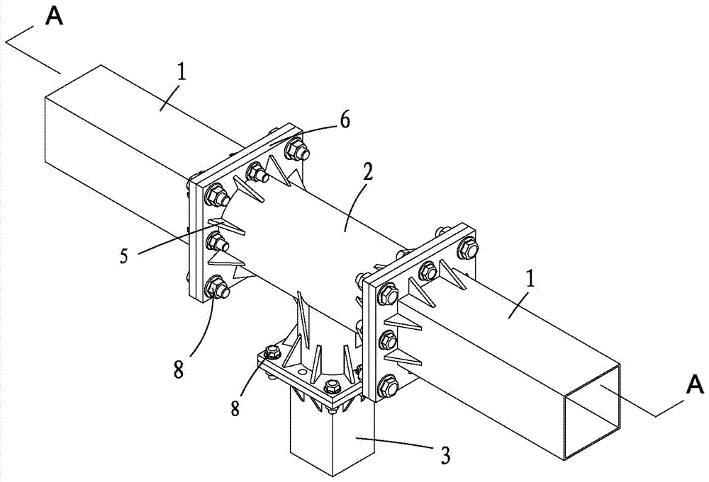
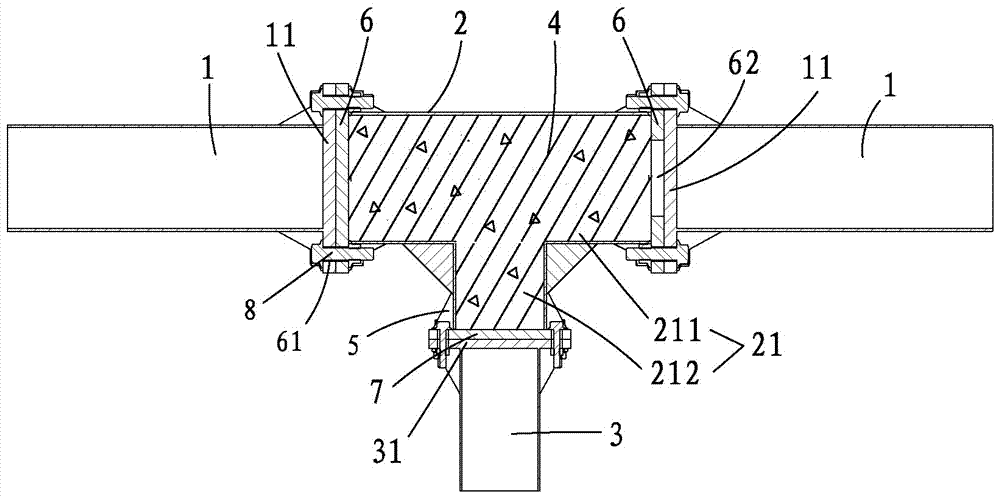
[0030] Such as Figure 1 to Figure 4 As shown, the assembly structure of a steel tube concrete composite truss of the present invention includes at least one main leg steel tube 1, at least one steel tube concrete node 2, and at least one pipe attachment 3, and the steel tube concrete node 2 includes a steel tube node 21, so Described steel pipe node 21 is made up of a chord 211, at least one web 212, and described chord 211 and web 212 are all filled with concrete 4 (such as image 3 As shown), a nozzle of each web 212 is welded on the wall of the chord 211 and communicated with each other, a plurality of stiffeners 5 are welded between the web 212 and the chord 211, the Stiffeners 5 improve the stress conditions at the joints of each component, significantly improve the local stability and stiffness of the joints, increase the bearing capacity and ductility, and effectively avoid buckling at the joints; the two nozzles of the chord 211 are welded There is a first connecting...

Embodiment 2

[0037] see Figure 3 to Figure 4 As shown, the assembly node of a composite steel pipe concrete truss of the present invention, the assembly node includes a steel pipe concrete node 2, and the steel pipe concrete node 2 includes a steel pipe node 21, and the steel pipe node 21 is composed of a chord 211, at least one web Rods 212, the chords 211 and the webs 212 are filled with concrete 4 (such as image 3 As shown), a nozzle of each web 212 is welded on the wall of the chord 211 and communicated with each other, and a plurality of stiffeners 5 are welded between the web 212 and the chord 211, obviously The local stability and rigidity of the connection are improved, the bearing capacity and ductility are improved, and the buckling of the connection is effectively avoided; the two nozzles of the chord 211 are welded with a first connecting plate 6, and the first connecting plate 6 A plurality of stiffeners 5 are welded between the top and the chord 211, a plurality of bolt ho...


PUM


Abstract

The invention provides an assembly structure and assembly joint of a steel pipe concrete combined truss. The assembly structure comprises at least one main limb steel pipe, at least one steel pipe concrete joint and at least one joining pipe. Each steel pipe concrete joint comprises a steel pipe joint body composed of a chord member and at least one web member. The chord members and the web members are filled with concrete. A pipe opening of each web member is arranged on the wall of the corresponding chord member and communicates with the wall of the corresponding chord member mutually. First connecting plates are arranged at the two pipe openings of each chord member. More than one bolt hole is formed in each first connecting plate. A second connecting plate is arranged on the other pipe opening of each web member. More than one bolt hole is formed in each second connecting plate. The main limb steep pipes are connected with the first connected plates in a locking mode through bolts. The joining pipes are connected with the second connecting plates in a locking mode through bolts. Concrete pouring holes are formed in at least any one of the first connecting plates and the second connecting plates. The transporting, mounting and detaching difficulty of equipment is reduced greatly, the construction period is shortened significantly, the construction cost is reduced, economy and high efficiency are achieved, the application range is wide, and the industrialization degree is high.

Description

technical field [0001] The invention relates to the technical field of prefabricated assembly structures in civil engineering, in particular to an assembly structure and assembly nodes of a steel pipe concrete composite truss. Background technique [0002] The traditional steel pipe truss is mainly composed of the main limb and the attached pipe, and the connection between the main limb and the attached pipe is usually welded. Before welding, it is necessary to use wire cutting to cut out intersecting lines at the end of the pipe according to the geometric characteristics of the main limb and the pipe to complete the welding. Limited by on-site construction conditions, welding often needs to be completed in the factory, so the workload is heavy, the production cost is high, and the processing cycle is long. Low. For large-scale truss structures, due to the cross-section and self-heavy weight of the rods, the requirements for hoisting machinery are very high, and many weldi...

Claims


Application Information

Patent Timeline
IPC IPC(8): E04C3/04E04B1/58
CPCE04B1/58E04C3/04
Inventor 郑永乾李振郑莲琼赖鹏松赵剑翁永晖
Owner FUJIAN UNIV OF TECH
Learn More