Ultra-short chirped pulse time domain phase and frequency domain phase measurement method and system

A technology of ultra-short chirp and phase measurement, which is applied in measurement devices, measurement optics, optical radiation measurement, etc., can solve problems such as insufficient measurement capability, low work efficiency, and complicated measurement methods, and achieve the goal of improving work efficiency and measurement capability Effect

Active Publication Date: 2017-08-11
TSINGHUA UNIV
View PDF4 Cites 9 Cited by
  • Summary
  • Abstract
  • Description
  • Claims
  • Application Information

AI Technical Summary

Problems solved by technology

[0005] The present invention provides a method and system for measuring ultra-short chirped pulse time-domain phase and frequency-domain phase that overcome the above problems or at least partially solve the above problems, and solve the work efficiency caused by complex measurement methods and cumbersome data processing in the prior art Problems with low and insufficient measurement capabilities

Method used


Image

  • Ultra-short chirped pulse time domain phase and frequency domain phase measurement method and system
  • Ultra-short chirped pulse time domain phase and frequency domain phase measurement method and system
  • Ultra-short chirped pulse time domain phase and frequency domain phase measurement method and system

Examples


Embodiment 1

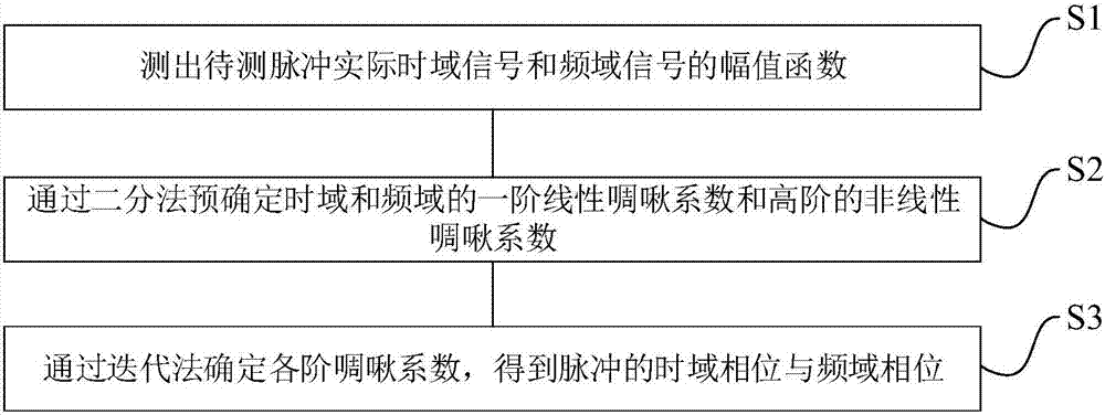
[0046] Such as figure 1 As shown in the figure, a method for measuring ultrashort chirped pulse time-domain phase and frequency-domain phase is shown in the figure, including:

[0047] S1. Measure the amplitude function of the actual time-domain signal and frequency-domain signal of the pulse to be measured;

[0048] S2. Predetermining first-order linear chirp coefficients and high-order nonlinear chirp coefficients in the time domain and frequency domain by dichotomy;

[0049] S3. Determine the chirp coefficients of each order by an iterative method to obtain the time-domain phase and frequency-domain phase of the pulse.

[0050] As preferably, said step S2 specifically includes:

[0051] S21. Predetermining the first-order linear chirp coefficients in the time domain and frequency domain;

[0052] S22. Predetermining N-order nonlinear chirp coefficients in time domain and frequency domain;

[0053]S23. Keep the N-order nonlinear chirp coefficients unchanged, and repeated...

Embodiment 2

[0078] This embodiment provides an ultrashort-chirped time-domain pulse phase and frequency-domain phase measurement system, using the method described in Embodiment 1, including:

[0079] The actual amplitude function acquisition module is used to obtain the amplitude function of the actual time domain signal and frequency domain signal;

[0080] The chirp coefficient determination module is used to determine linear chirp coefficients and high-order nonlinear chirp coefficients in the time domain and frequency domain through a dichotomy method and an iterative method.

Embodiment 3

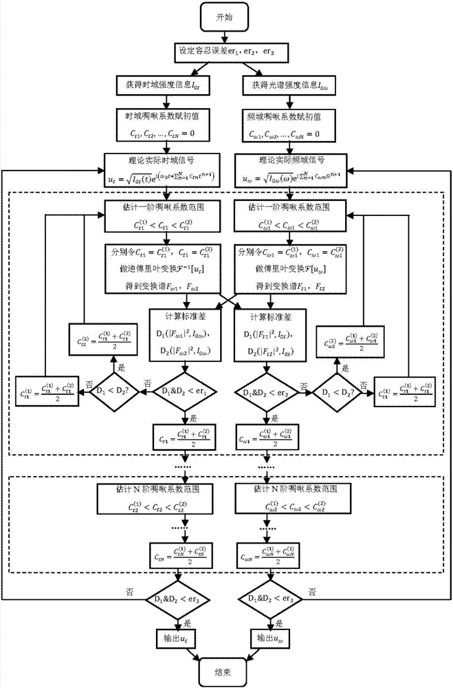
[0082] In this embodiment, what is to be tested is a quasi-monochromatic chirped pulse of hundreds of picoseconds, such as figure 2 As mentioned, the specific implementation steps are as follows:

[0083] Firstly, the time-domain intensity information and spectral intensity information of the pulse are measured with an oscilloscope and a spectrometer respectively, and the measured signal is normalized to obtain the amplitude function of the actual time-domain signal and spectral signal.

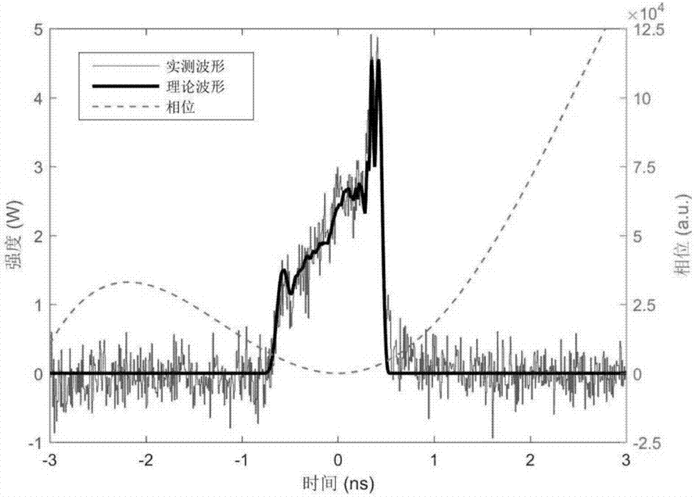
[0084] Assume that the measured time-domain intensity waveform and frequency-domain spectral intensity are normalized and denoted as I 0t , I 0ω ,Such as image 3 and Figure 4 shown in ; assuming that the chirp coefficients C of each order in the time domain t1 , C t2 , C t3 ...; the chirp coefficient C of each order of the spectrum ω1 , C ω2 , C ω3 …; Let the center frequency be ω 0 ;remember Then the actual time domain signal and frequency domain signal should be:

[0085] ...


PUM


Abstract

The invention provides an ultra-short chirped pulse time domain phase and frequency domain phase measurement method and system. The method comprises steps of S1, measuring the amplitude functions of the actual time domain signal and the frequency domain signal of the to-be-measured pulse; S2, determining the first order linear chirp coefficient and the high order nonlinear chirp coefficient in the time domain and frequency domain by dichotomy; and S3, determining the chirp coefficient of each order by the iterative method to obtain the time domain phase and the frequency domain phase of the pulse. The time domain strength waveform information and the spectral intensity information of the pulse are measured and the iterative algorithm is used to determine the chirp coefficient of each order, the complex interference optical path is not required, and the instrument of directly measuring the phase is not required. Only the time domain strength waveform information and the spectral intensity information of the pulse are needed to be measured, and the linear chirp coefficient and the high order nonlinear chirp coefficient of the time domain and the frequency domain can be measured at the same time.

Description

technical field [0001] The present invention relates to the field of ultrashort chirped optical pulses, and more specifically, to a method and system for measuring time domain phase and frequency domain phase of ultrashort chirped pulses. Background technique [0002] Ultrashort laser pulses generally refer to light pulses with sub-nanosecond to femtosecond pulse widths, which are widely used in various fields such as physics, chemistry, materials, biology, national defense, and industrial processing due to their ultrafast and high peak power characteristics. . Ultrashort pulses are generally generated by mode-locked lasers. The pulses are formed by the coherent superposition of phase-locked longitudinal modes. In the actual mode-locked laser construction and pulse amplification process, affected by various devices, each longitudinal mode of the ultrashort pulse It is impossible to completely lock the phase to be consistent, and the actual ultrafast pulse must have phase di...

Claims


Application Information

Patent Timeline
Patent Type & Authority Applications(China)
IPC IPC(8): G01J9/00G01J11/00
CPCG01J9/00G01J11/00G01J2009/006
Inventor 申艺杰巩马理付星
Owner TSINGHUA UNIV
Why Eureka
Try Eureka