Multifunctional body fluid collector

A bodily fluid collection, multi-functional technology, applied in the field of collectors, can solve the problems of body fluid overflow, inconvenient operation, long time-consuming, etc., and achieve the effects of not easy to deform, accurate volume, and objective data

Pending Publication Date: 2017-08-15
无锡康特佳健康科技有限公司
View PDF1 Cites 0 Cited by
  • Summary
  • Abstract
  • Description
  • Claims
  • Application Information

AI Technical Summary

Problems solved by technology

[0003] 1. To take samples or inject drugs, the body fluid collector needs to be removed as a whole, which is inconvenient and time-consuming to operate;
[0004] 2. The soft plastic bag used as a storage device will be deformed during use, which will affect the display of the internal liquid volume reading;
[0005] 3. When the body fluid is full, it will overflow. Even if it is replaced in time, it may cause pollution and pose a health hazard.

Method used


Image

  • Multifunctional body fluid collector
  • Multifunctional body fluid collector
  • Multifunctional body fluid collector

Examples


Embodiment 1

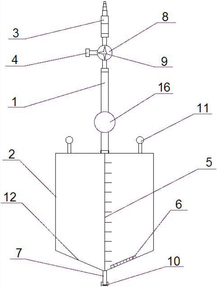
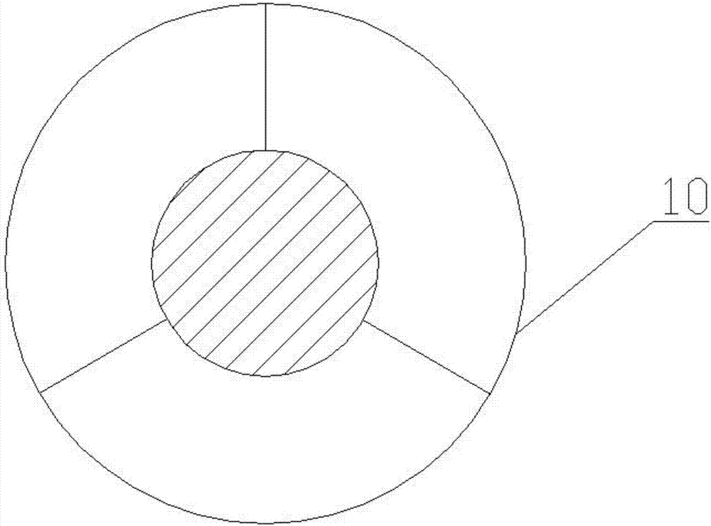
[0025] like figure 1 As shown, a multifunctional body fluid collector includes a diversion tube 1 and a liquid reservoir 2, the front end of the diversion tube 1 is provided with a collection terminal 3, and the rear end of the diversion tube 1 is connected to the liquid reservoir 2; The front end of the pipe 1 is provided with a three-way structural member, one end of the three-way structural member is connected to the diversion pipe 1, and the other end is connected to the collecting terminal 3, and the remaining end of the three-way structural member is used as the connecting end 4 connected with the external equipment; the liquid reservoir 2. Use a hard cuboid or cylindrical plastic bottle. The side surface of the plastic bottle is provided with a scale line 5 and a color card 6. The bottom of the plastic bottle is provided with a discharge port 7, and the discharge port 7 is provided with a locking structure.

[0026] The collecting end is used to connect the drainage tub...

Embodiment 2

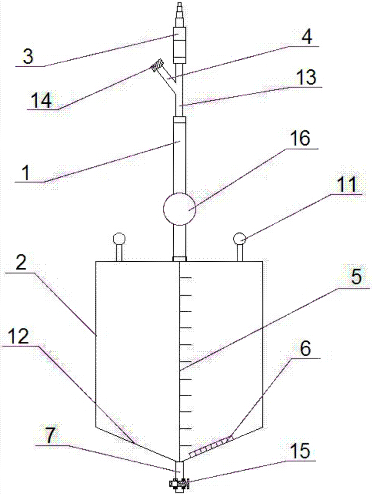
[0034] The difference between this embodiment and Embodiment 1 is that: the three-way structure is a Y-shaped joint 13, and the connecting end of the Y-shaped joint 13 is provided with a threaded screw cap 14, which only needs to be unscrewed when connecting external equipment; The stop structure is a transverse cut-off piston 15, the piston rod of the transverse cut-off piston 15 is provided with a vertical through hole, the piston rod can reciprocate along any radial direction of the discharge port, the piston rod is pulled out, and the liquid flows out through the vertical through hole , the distance you pull out can control the flow.

[0035] A multifunctional body fluid collector of the present invention is provided with a three-way structure, which is convenient for sampling or injecting medicine. The storage device adopts a hard plastic bottle and is equipped with an excretion port, which is not easy to deform and does not overflow. In addition, the storage device is pro...


PUM


Abstract

The invention provides a multifunctional body fluid collector comprising a diversion pipe and a fluid storage device. The front end of the diversion pipe is provided with a collection end head; the back end of the diversion pipe is connected with a fluid storage device; a tee-joint structure member is arranged in any position of the diversion pipe; any two ends of the tee-joint structure member connect the diversion pipe; the rest end of the tee-joint structure member works as an introduction end connected with an external device; the fluid storage device is a hard cubic or cylindrical plastic bottle; scales lines and a color card are arranged on the side surface of the plastic bottle; a scavenge port is arranged on the bottom of the plastic bottle; and the scavenge port is provided with a lock structure member. With the tee-joint structure on the multifunctional body fluid collector, sampling or medicine injection can be facilitated; the storage device is achieved by a hard plastic bottle and equipped with the scavenge port, and deformation and overspill can be avoided; with the scale lines and the color card mounted on the storage device, the volume can be accurately calculated and data can be more objective; and fluid color can be compared and observed, so a patient body condition can be learnt.

Description

technical field [0001] The invention relates to a collector, in particular to a multifunctional body fluid collector. Background technique [0002] The body fluid collector is an important medical device used to collect body fluid after surgery. The traditional body fluid collector is composed of a drainage tube and a soft plastic bag. This structure has the following defects: [0003] 1. To take samples or inject drugs, the body fluid collector needs to be removed as a whole, which is inconvenient and time-consuming to operate; [0004] 2. The soft plastic bag used as a storage device will be deformed during use, which will affect the display of the internal liquid volume reading; [0005] 3. When the body fluid is full, it will overflow. Even if it is replaced in time, it may cause pollution and pose a health hazard. Contents of the invention [0006] The technical problem to be solved by the present invention is to overcome the existing defects and provide a multifunc...

Claims


Application Information

Patent Timeline
IPC IPC(8): A61M1/00
CPCA61M1/0001A61M1/82
Inventor 陆建芳芦慧孙嘉悦孙开宁
Owner 无锡康特佳健康科技有限公司
Why Eureka
Try Eureka