CO2 energy storage device for realizing circular power generation by using biomass combustion

An energy storage device and cyclic power generation technology, which is applied in the direction of fuel, combustion method, combustion type, etc., which are burned in a molten state, can solve problems such as insufficient efficiency, and achieve the effects of flexible adjustment and utilization, pollution reduction, and high thermal efficiency.

Pending Publication Date: 2017-08-15
长沙紫宸科技开发有限公司
View PDF5 Cites 0 Cited by
  • Summary
  • Abstract
  • Description
  • Claims
  • Application Information

AI Technical Summary

Problems solved by technology

The device uses a hot air fan for heat exchange, which is not efficient enough in actual use and has certain limitations

Method used


Image

  • CO2 energy storage device for realizing circular power generation by using biomass combustion
  • CO2 energy storage device for realizing circular power generation by using biomass combustion
  • CO2 energy storage device for realizing circular power generation by using biomass combustion

Examples


Embodiment 1

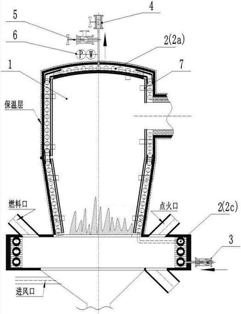
[0036] Such as figure 1 As shown, the present invention provides a CO that utilizes biomass combustion to realize cycle power generation 2 Energy storage device, biomass furnace 1 is boiling furnace, CO 2 Fluid energy storage mechanism 2, check valve 3, regulating valve 4, safety valve 5, temperature and pressure sensor 6, support and hanger 7; the fluidized fluidized furnace also includes a high temperature zone, a fuel port, an air inlet, an ignition port, and an ash outlet , smoke outlet and preheating zone, the fuel port, air inlet, ignition port, and ash outlet are all arranged in the preheating zone; the high temperature zone is adjacent to the preheating zone; the CO 2 The fluid energy storage mechanism 2 adopts a plate heat exchanger 2a, which is fixed on the inner wall of the fluidized fluidized furnace or embedded in the refractory material of the inner wall through the support bracket 7, and the outer wall of the fluidized fluidized furnace and the CO 2 An insulat...

Embodiment 2

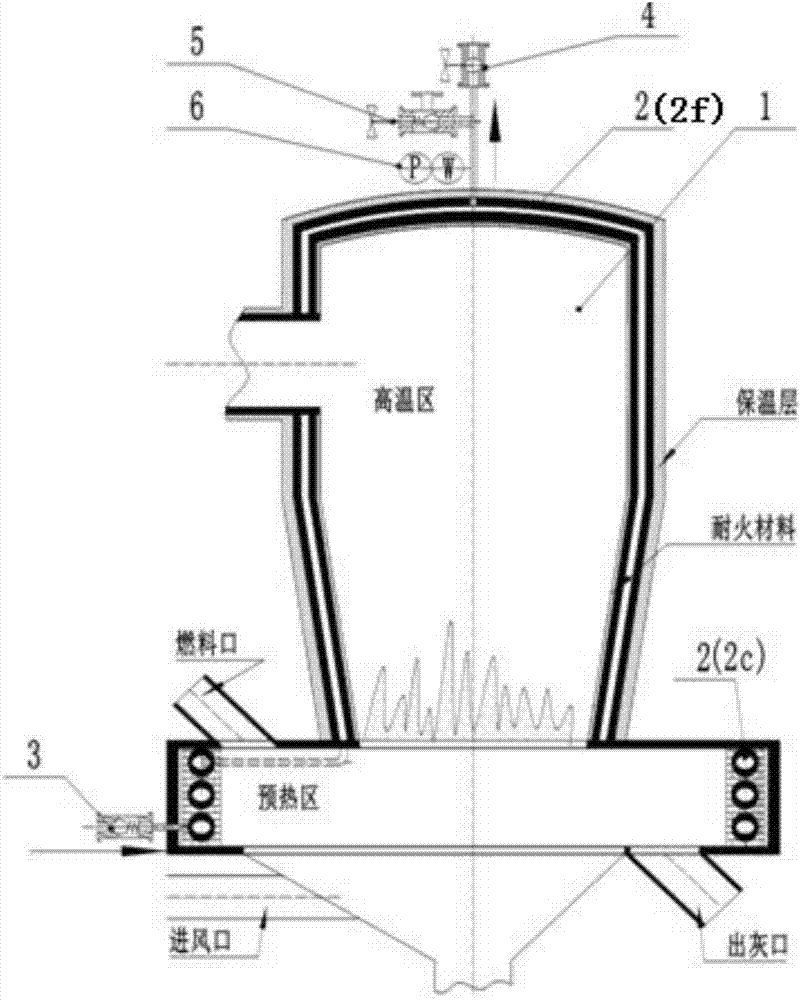
[0040] Such as figure 2 As shown, the difference between embodiment 2 and embodiment 1 is that the CO 2 The fluid energy storage mechanism 2 adopts a jacketed heat exchanger 2f, and the jacketed heat exchanger 2f is embedded and fixed on the inner wall of the fluidized furnace or embedded in the refractory material of the inner wall, and the outer wall of the fluidized furnace and the CO 2 An insulation layer is arranged between the fluid energy storage mechanism 2; the CO 2 The fluid energy storage mechanism 2 adopts a disc-type hollow tube heat exchanger 2c, which is fixed on the inner wall of the preheating zone of the fluidized furnace or embedded in the inner wall refractory material.

Embodiment 3

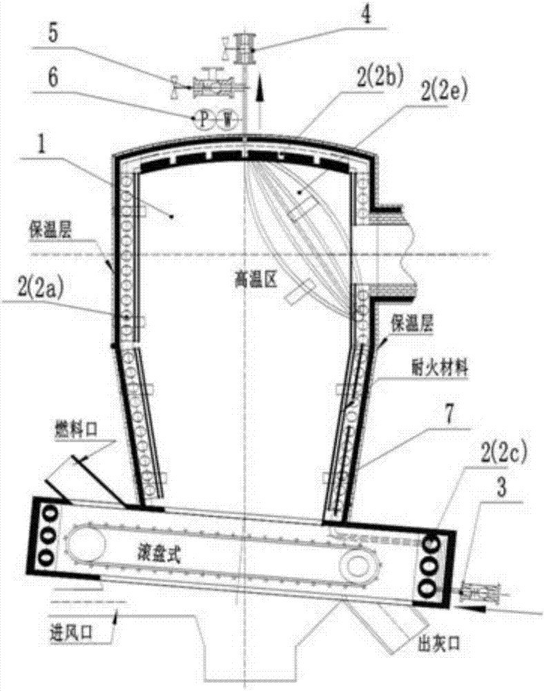
[0042] Such as image 3 As shown, the difference between embodiment 3 and embodiment 1 is that the biomass furnace 1 is a disc furnace, and the CO 2 The fluid energy storage mechanism 2 is composed of various forms. The plate heat exchanger 2a is fixed by a hanger 7 on the inner wall of the disc furnace or in the refractory material of the inner wall, and is fixed by a hanger 7 on the inner top of the disc furnace. There is a box-type heat exchanger 2b, and a shell-and-tube heat exchanger 2e is fixed at the smoke outlet of the disc furnace through a hanger 7, and a disc-type hollow tube heat exchanger is arranged in the preheating zone of the disc furnace 2c.

[0043] CO above 2 The fluid energy storage mechanism 2 includes a combination of a plate heat exchanger 2a, a box heat exchanger 2b, a shell and tube heat exchanger 2e, and a disc hollow tube exchanger 2c, and the working medium is CO 2 fluid.


PUM


Abstract

The invention provides a CO2 energy storage device for realizing circular power generation by using biomass combustion. The CO2 energy storage device is used for converting high-temperature heat energy stored energy, generated by direct absorption of the biomass combustion by a low-pressure liquid-state CO2 fluid, to a supercritical CO2 fluid, and comprises a biomass furnace, a CO2 energy storage mechanism, a check valve and an adjusting valve; the CO2 energy storage mechanism is fixed in the biomass furnace or embedded in an inner wall refractory material; the check valve and the adjusting valve are both arranged out of the biomass furnace; the check valve communicates with an inlet of the CO2 energy storage mechanism; the adjusting valve communicates with an outlet of the CO2 energy storage mechanism; and the CO2 energy storage mechanism uses a CO2 fluid as a working medium. The device locally uses a lot of renewable low-carbon biomass fuels generated in vast national countries as energy for energy storage of the low-temperature CO2 fluid as the high-pressure heat-state supercritical CO2 fluid to generate electricity for a CO2 power generating unit, and is simple in structure, low in self energy consumption, low in investment and low in operation cost.

Description

technical field [0001] The invention relates to the technical field of low-carbon and energy utilization equipment, in particular to a CO 2 energy storage device. Background technique [0002] Climate change has become one of the issues affecting human survival and development, and carbon dioxide emitted by industry is considered to be the main cause of climate warming. As the largest developing country in the world, our country uses coal as its primary energy and thermal power as its secondary energy as its energy structure. With the rapid growth of economic aggregate, the CO of primary energy and secondary energy 2 Emissions are characterized by rapid growth and large volumes. In response to climate change, it has become a consensus to develop low-carbon energy, especially renewable energy and new energy. Biomass power generation and supercritical carbon dioxide power generation have received widespread attention. [0003] At present, the existing biomass power generat...

Claims


Application Information

Patent Timeline
Patent Type & Authority Applications(China)
IPC IPC(8): F23C10/00F24H3/08
CPCF23C10/00F24H3/088
Inventor 尹小林
Owner 长沙紫宸科技开发有限公司
Why Eureka
Try Eureka