
Automatic water diversion fire truck

A technology of automatic water diversion and fire trucks, applied in fire rescue and other directions, can solve problems such as impact on operation efficiency, disadvantages, and increase in quantity, and achieve the effect of ensuring the effect of water diversion and reducing the effect of automation

Active Publication Date: 2022-03-15
JIEDA FIRE PROTECTION VEHICLE EQUIP CO LTD SUZHOU CITY
View PDF11 Cites 2 Cited by
  • Summary
  • Abstract
  • Description
  • Claims
  • Application Information

AI Technical Summary

Problems solved by technology

But this CN204815475U still has the following shortcoming: one, because the vehicle-mounted pump as water diversion mechanism can not be directly placed in the water source and needs to divert water by the transition of the water pump that is placed in the water source and is located on the buoyancy tank, thereby the number of pumps increases , which is not conducive to saving energy consumption, nor is it conducive to reducing the cost of fire-fighting facilities and significantly increases the workload of daily maintenance; second, because in actual use, it is necessary for firefighters to put the floating tank together with the water pump into a water source such as a river Therefore, on the one hand, the operating efficiency is affected and the time for fire fighting and disaster relief may be delayed. On the other hand, the firefighters have a high intensity of work. Together with the water pump, it is stored on the fire fighting vehicle; thirdly, since the buoy and the water pump are in a free-floating state without tube bundles in the water area such as the aforementioned river, when it is driven to the shore of the water area by wind and waves, there is a risk of affecting the water diversion effect. Although it can be artificially driven away from the shore area by on-site firefighters, such operations will also increase the work intensity of firefighters

Method used


Image

  • Automatic water diversion fire truck
  • Automatic water diversion fire truck
  • Automatic water diversion fire truck

Examples


Embodiment Construction

[0025] In order to understand the technical essence and beneficial effects of the present invention more clearly, the applicant will describe in detail the following examples, but the descriptions of the examples are not intended to limit the solutions of the present invention. Equivalent transformations that are only formal but not substantive should be regarded as the scope of the technical solution of the present invention.

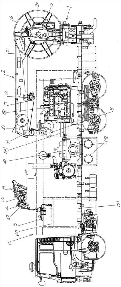
[0026] In the following descriptions, all concepts related to directionality or orientation of up, down, left, right, front and back are based on figure 1 The shown position status is a reference, so it cannot be understood as a special limitation on the technical solution provided by the present invention.

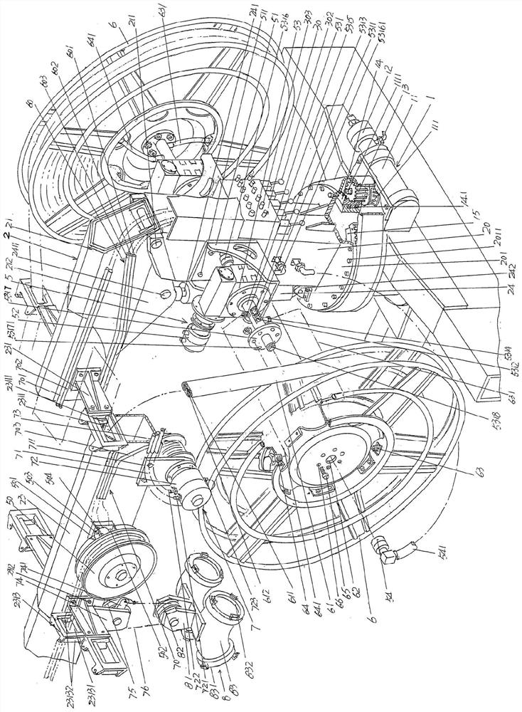
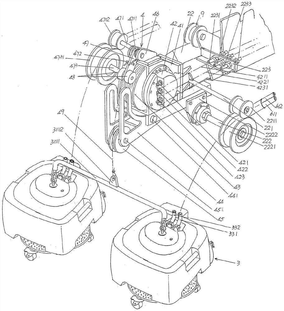
[0027] See figure 1, shows a vehicle body 10. According to professional knowledge, the vehicle body 10 has a chassis 101. Since the vehicle body 10 belongs to the prior art, the applicant will not further explain it. Shown is a hollow column 20 ...


PUM


Abstract

An automatic water diversion firefighting vehicle, comprising a vehicle body; a column is arranged on a rotary driving mechanism of the column, on which a hydraulic oil distribution valve is fixed, the hydraulic oil distribution valve is connected with a hydraulic oil pipe of a hydraulic station, and the hydraulic station is arranged on the chassis of the vehicle body Above, the column rotation drive mechanism is set on the chassis and is located at the right end of the chassis; the lifting mechanism is connected with the column; the water diversion mechanism is connected with the traction mechanism, and the traction mechanism is set on the lifting mechanism; On the front and rear sides of the column, each is connected with a hoisting coil of oil pipe, on which the hoisting coil oil pipe is arranged, and the water diversion mechanism is connected with the oil pipe of the hoisting coil; the lifting mechanism of the pulley seat is arranged on the lifting mechanism and distributed with the hydraulic oil The valve oil circuit is connected; the fire water lead-out mechanism is pulled by the pulley seat lifting mechanism and connected with the water diversion mechanism. The automation effect is ideal, and the work intensity is reduced; it can avoid sinking and be affected by the silt in the water; it can keep the water diversion mechanism away from the shore to ensure the water diversion effect.

Description

technical field [0001] The invention belongs to the technical field of firefighting facilities, and in particular relates to an automatic water diversion firefighting vehicle. Background technique [0002] As known in the industry, fire trucks, especially water diversion fire trucks (also known as water supply fire trucks), are usually equipped with water diversion pumps (also known as water supply pumps). For this, please refer to the recommended Chinese patent authorization announcement number CN203043382U, which is not limited to examples. "Water diversion system and fire engine", when the water diversion fire engine arrives at the fire scene and parks near a place with natural water sources such as rivers, lakes, ditches and ponds, etc., the end of the water intake pipeline connected to the water diversion pump is led to the aforementioned natural water source. When the water diversion pump is in working condition, the fire-fighting water is led to the fire pump through...

Claims


Application Information

Patent Timeline
Patent Type & Authority Patents(China)
IPC IPC(8): A62C27/00A62C31/00
CPCA62C27/00A62C31/00
Inventor 张建明
Owner JIEDA FIRE PROTECTION VEHICLE EQUIP CO LTD SUZHOU CITY
Learn More