
A kind of back pressure type volume reduction molding equipment and its operation method

A molding equipment and back pressure technology, applied in the field of back pressure volume reduction molding equipment and its operation, can solve the problems of waste of energy consumption, low production efficiency, etc., to achieve reduced energy consumption, stable operation of the equipment, and convenient and quick operation process Effect

Active Publication Date: 2018-12-18
XUZHOU UNIV OF TECH
View PDF5 Cites 0 Cited by
  • Summary
  • Abstract
  • Description
  • Claims
  • Application Information

AI Technical Summary

Problems solved by technology

[0003] Molding machines involve a wide range of fields, but at present, the energy consumption of molding machines in China accounts for as high as 12% of the entire industrial energy consumption. Among the most widely used conventional molding machine equipment, more than three quarters are hot air molding machines. The waste of energy consumption of similar molding machine equipment is very serious, and the manual rolling extrusion method is often used for molding production, and the production efficiency is low

Method used


Image

  • A kind of back pressure type volume reduction molding equipment and its operation method
  • A kind of back pressure type volume reduction molding equipment and its operation method
  • A kind of back pressure type volume reduction molding equipment and its operation method

Examples


Embodiment Construction

[0031] The present invention will be further described below in conjunction with accompanying drawing.

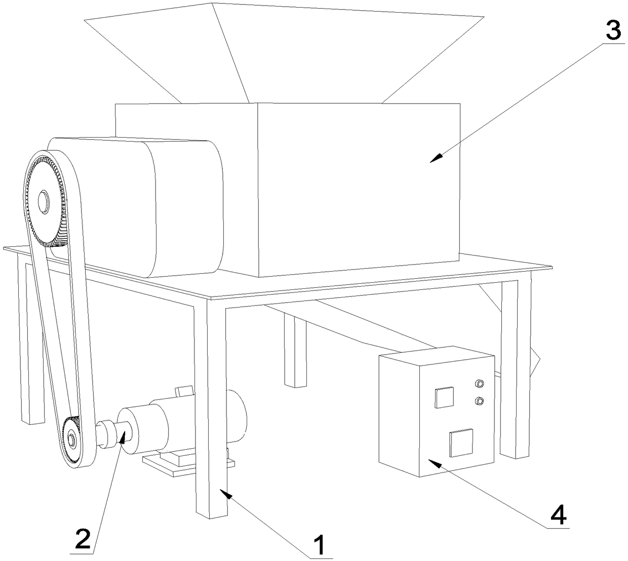
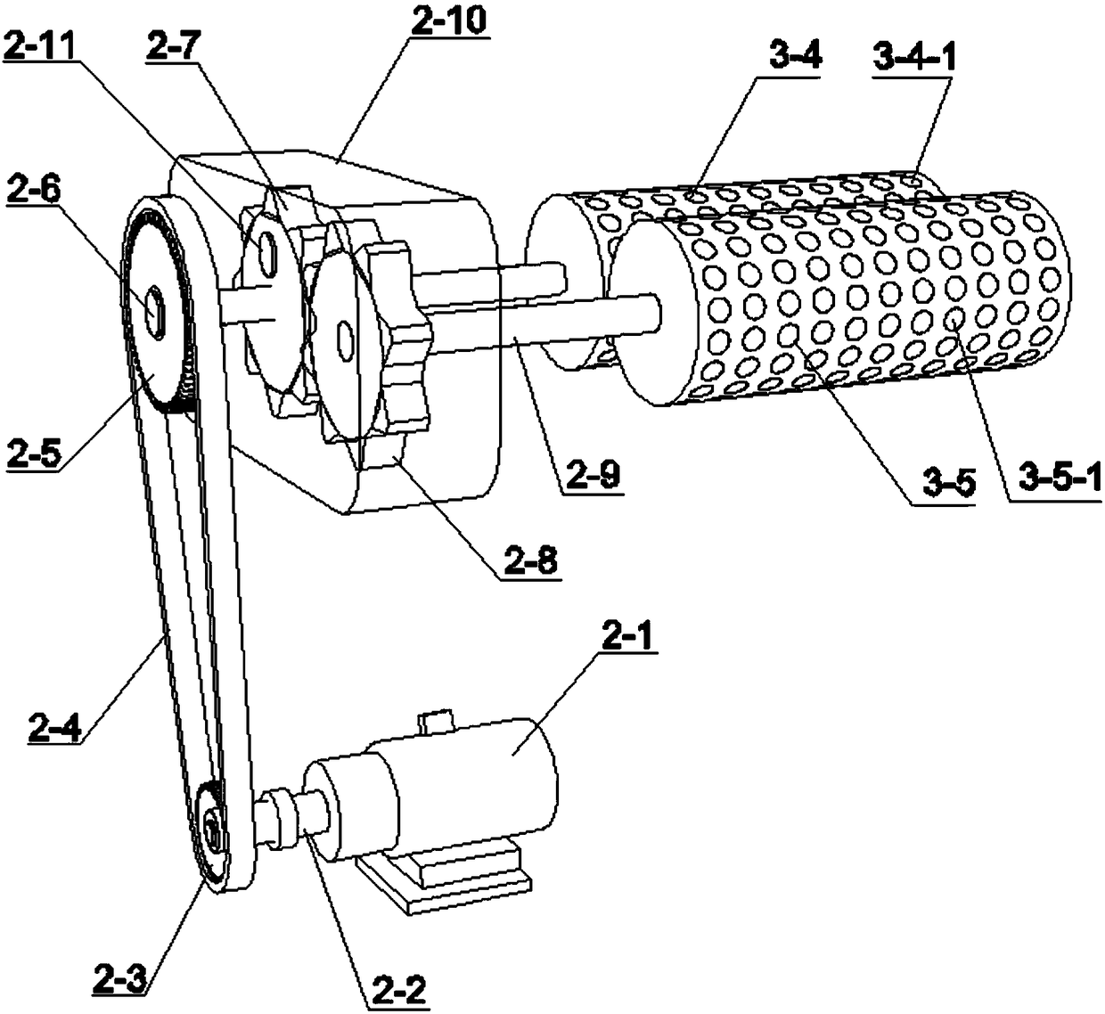
[0032] Such as figure 1 As shown, a back pressure volume reduction molding equipment includes a fixed bracket 1, a transmission mechanism 2 and a back pressure volume reduction molding mechanism 3, such as figure 2 As shown, the transmission mechanism 2 includes a transmission motor 2-1, a driven pulley central shaft 2-6 and a negative pressure gear central shaft 2-9; the transmission motor 2-1 is fixedly arranged under the fixed bracket 1, and its The output end is fixedly connected to one end of the transmission motor main shaft 2-2, and the other end of the transmission motor main shaft 2-2 is fixedly fitted with a driving pulley 2-3; the driven pulley central shaft 2-6 and the negative pressure gear central shaft 2 -9 is arranged on fixed support 1 top side by side, and the left end of driven pulley central shaft 2-6 is fixedly sleeved with driven pulley 2-5, and driv...


PUM


Abstract

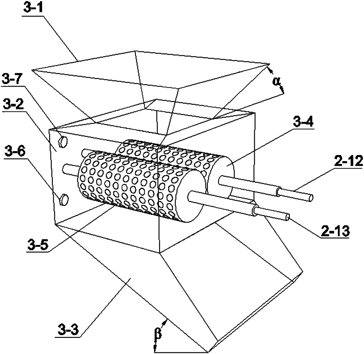
The invention discloses a back pressure type volume reduction forming equipment and an operating method thereof. A drive forming roller shaft (3-4) and a driven forming roller shaft (3-5) which rotate oppositely are arranged abreast in a back pressure type volume reduction forming bin (3-2); forming grooves are both formed in the two forming roller shafts; hollow inner cavities of the two forming shafts are both connected with a vacuum pump; and a high pressure gas generator (3-6) in which high pressure mixed gas is filled is also arranged in the back pressure type volume reduction forming bin (3-2). The operating method comprises the following steps: 1) starting a transmission motor (2-1) to ensure that the drive forming roller shaft (3-4) and the driven forming roller shaft (3-5) oppositely rotate; 2) forming a negative pressure environment in the back pressure type volume reduction forming bin (3-2); 3) pouring raw materials into a back pressure type volume reduction forming mechanism (3), and discharging particles which are obtained by processing the raw materials out of a discharging bin (3-3). According to the equipment and the operating method, the automatic degree and the forming efficiency of the forming equipment can be improved, and the energy consumption waste is reduced.

Description

technical field [0001] The invention relates to a molding device and its operating method, in particular to a back pressure type volume reduction molding device and its operating method. Background technique [0002] The forming machine is widely used in the processing of granular fertilizers, retentate and other products. The forming process is: the dry material is agglomerated into dense and hard material blocks under the extrusion of the rotating roller, and the material block is crushed and screened by the rotating roller to reach the final product. Granules for strength requirements. [0003] Molding machines involve a wide range of fields, but at present, the energy consumption of molding machines in China accounts for as high as 12% of the entire industrial energy consumption. Among the most widely used conventional molding machine equipment, more than three quarters are hot air molding machines. The waste of energy consumption of similar molding machine equipment is...

Claims


Application Information

Patent Timeline
Patent Type & Authority Patents(China)
IPC IPC(8): B02C4/08B02C4/40B02C4/42B02C23/28B02C23/40B02C25/00
CPCB02C4/08B02C4/40B02C4/42B02C23/28B02C23/40B02C25/00
Inventor 梁峙肖扬徐永铭
Owner XUZHOU UNIV OF TECH
Learn More