

Fast servo ultraprecise fly cutting machining method for brittleness material complex curved surface
A technology for complex curved surfaces and brittle materials, applied in the field of machining, it can solve the problems of easy cutting damage of brittle materials, and achieve the effect of avoiding brittle cracking, fast and stable cutting, and ensuring surface quality and optical performance.
- Summary
- Abstract
- Description
- Claims
- Application Information
AI Technical Summary
Problems solved by technology
Method used
Image

Examples
Embodiment Construction
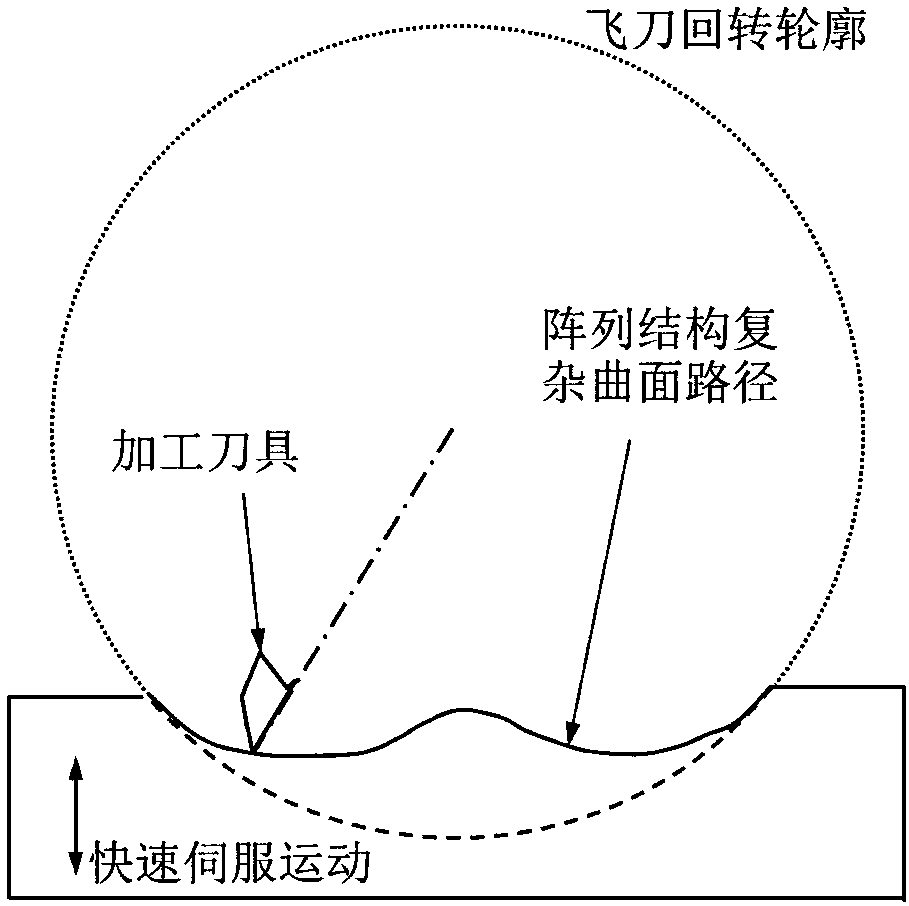
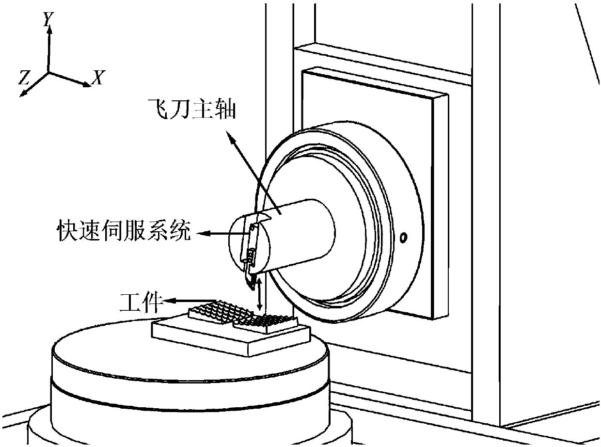
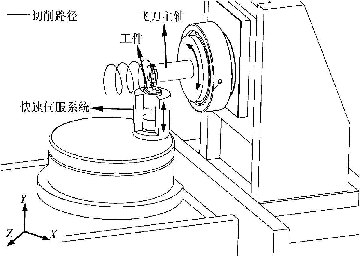
[0020] Aiming at the difficulty in processing complex curved surfaces of brittle materials with poor surface quality and other difficulties, the present invention proposes a processing method combining fast servo and flying tool, that is, the diamond turning tool is vertically installed on the spindle of the ultra-precision flying tool, and coupled with the fast servo motion Realize high-speed machining of complex curved surfaces. This method can realize rapid and high-quality generation of brittle material microstructure arrays and other complex surfaces, avoiding impurities and defects that may be introduced in traditional grinding. During the processing, the high speed of the flying knife spindle can be guaranteed, and the frequency conversion and amplitude cutting of the processed surface can be realized through fast servo movement, and the single removal amount of material during the cutting process can be controlled to realize efficient and low-damage processing of brittl...
PUM
 Abstract
Description
Claims
Application Information