
Laser welding shielding gas nozzle with defocusing amount positioning function

A technology of laser welding and shielding gas, applied in laser welding equipment, welding equipment, metal processing and other directions, can solve the problem of poor measurement and positioning of defocus, and achieve the effect of good gas shielding effect, convenient operation, and easy installation and disassembly.

Inactive Publication Date: 2017-08-18
CHINA ELECTRONIC TECH GRP CORP NO 18 RES INST
View PDF7 Cites 4 Cited by
  • Summary
  • Abstract
  • Description
  • Claims
  • Application Information

AI Technical Summary

Problems solved by technology

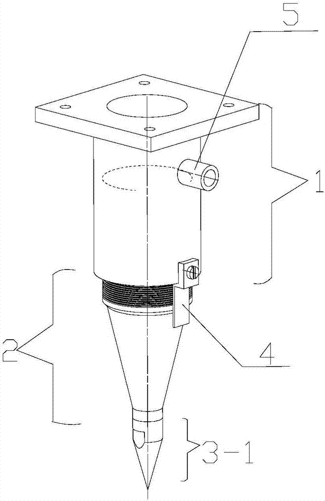
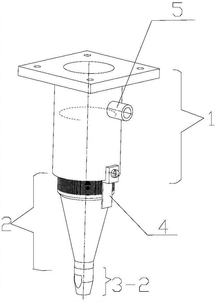
[0007] The technical problem to be solved by the present invention is to provide a shielding gas nozzle for laser welding with defocus positioning function. The laser welding shielding gas nozzle with defocus positioning function has a replaceable nozzle assembly, which can be replaced with a coaxial Measure the top to locate the defocus amount. At the same time, the side of the nozzle has a special measuring scale, which can accurately measure the distance value of the defocus amount. It solves the problem of poor defocus amount due to the welding head moving with the robot during robot laser welding. Measure the problem of positioning, and at the same time facilitate the establishment of accurate TCP points, providing reliable support for the implementation of the welding process

Method used


Image

  • Laser welding shielding gas nozzle with defocusing amount positioning function
  • Laser welding shielding gas nozzle with defocusing amount positioning function

Examples


Embodiment Construction

[0028] In order to further understand the invention content, characteristics and effects of the present invention, the following examples are given, and detailed descriptions are as follows in conjunction with the accompanying drawings:

[0029] see Figure 1 to Figure 2 , a gas nozzle with a defocus positioning function with a defocus positioning function, comprising:

[0030] Mounting base 1; said mounting base 1 includes a rectangular connecting plate for connecting with a welding head, and a first cylinder integrally connected with said connecting plate, and said connecting plate is provided with a circular hole through which a laser passes; said The inner diameter of the circular hole is the same as that of the first cylinder and both are coaxial; the side of the first cylinder is provided with an air nozzle interface 5;

[0031] The main nozzle 2; the main nozzle 2 includes a second cylinder connected to the first cylinder and a third cylinder connected to the spray hea...


PUM


Abstract

The invention discloses a laser welding shielding gas nozzle with a defocusing amount positioning function. The laser welding shielding gas nozzle with the defocusing amount positioning function is characterized in that a mounting base comprises a connecting plate for connecting with a welding head and a first cylinder connected with the connecting plate as a whole; the connecting plate is provided with a round hole for allowing laser too pass through; the round hole and the first cylinder are the same in inner diameter, and are coaxial; an air nozzle joint is formed in the side edge of the first cylinder; a main nozzle comprises a second cylinder connected with the first cylinder, and a third cylinder connected with a nozzle module; the inner diameter of the second cylinder is larger than the inner diameter of the third cylinder; the second cylinder is connected with the third cylinder through a conical cylinder; the second cylinder and the second cylinder are coaxial; and the nozzle module is one of a nozzle or a coaxial tip. The laser welding shielding gas nozzle can be replaced as a coaxial measurement tip for positioning a defocusing amount; and meanwhile, a measuring staff is on the side body of the nozzle for precisely measuring a distance value of the defocusing amount, so that the problem of weak measurement and positioning of the defocusing amount is solved, meanwhile, a TCP point is convenient to built, and the welding process is convenient to perform.

Description

technical field [0001] The invention relates to the technical field of laser welding production of lithium-ion batteries, in particular to a laser welding shielding gas nozzle with a defocus positioning function. Background technique [0002] Laser welding is more and more widely used in the battery industry. In recent years, robotic laser welding systems have penetrated into the battery production industry. [0003] Laser welding is an efficient and precise welding method that uses a high-energy-density laser beam as a heat source. It has a small spot and small thermal deformation. In addition to welding metal materials, it can also weld parts in transparent shells, which is suitable for automation. [0004] Laser welding equipment generally consists of lasers, optical systems, laser processing machines, collimation systems, process medium transmission systems, and control systems. The optical system includes the transmission and focusing of the beam. The focusing is achie...

Claims


Application Information

Patent Timeline
IPC IPC(8): B23K26/14B23K26/24
CPCB23K26/1482B23K26/24B23K2101/36
Inventor 周春亮罗萍王捷谭玲生吴静魏乃达张洪凯尹航
Owner CHINA ELECTRONIC TECH GRP CORP NO 18 RES INST
Learn More