Eureka AIR delivers breakthrough ideas for toughest innovation challenges, trusted by R&D personnel around the world.

Exiting device for laser hybrid welding

A hybrid welding and laser welding head technology, used in laser welding equipment, welding equipment, metal processing equipment, etc., can solve the problems of heavy thermal crack tendency, more welding pores, and more welding spatter, and achieve a reduction in solidification speed and reduction of pores. , The effect of reducing welding spatter

Active Publication Date: 2017-08-18
UNITED WINNERS LASER CO LTD
View PDF7 Cites 12 Cited by
  • Summary
  • Abstract
  • Description
  • Claims
  • Application Information

AI Technical Summary

Problems solved by technology

[0006] In summary, the main purpose of the present invention is to make the laser beams emitted by semiconductor lasers and fiber lasers act on the same welding surface, thereby solving the problem of more air holes in traditional welding, heavier tendency of thermal cracks, more welding spatter, and thicker weld seams. Major technical problems, and provide a laser hybrid welding exit device

Method used


Image

  • Exiting device for laser hybrid welding
  • Exiting device for laser hybrid welding
  • Exiting device for laser hybrid welding

Examples


Embodiment 1

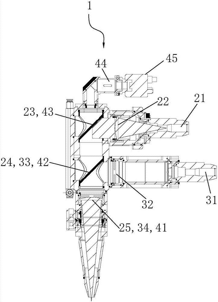
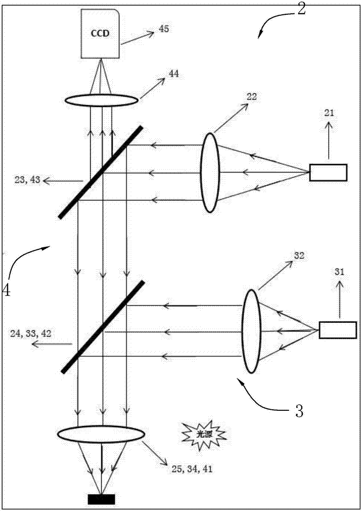
[0031] Such as Figure 1-9 As shown, the laser hybrid welding emitting device of the present invention includes a laser welding head 1, a semiconductor laser (not shown in the figure), and a fiber laser (not shown in the figure). The semiconductor laser and fiber laser are respectively connected to the laser welding head 1, the semiconductor laser is used to emit semiconductor laser to the laser welding head, and the fiber laser is used to emit fiber laser to the laser welding head. Such as figure 1 , figure 2 As shown in this embodiment, the optical path of the laser welding head 1 includes: a semiconductor optical path 2 , an optical fiber optical path 3 and a coaxial monitoring optical path 4 . The laser beam of the semiconductor optical path 2 and the laser beam of the optical fiber optical path 3 are focused at the focal point of the laser welding head, and combined into one beam for welding, and the welding position is illuminated by an external light source, and the ...

Embodiment 2

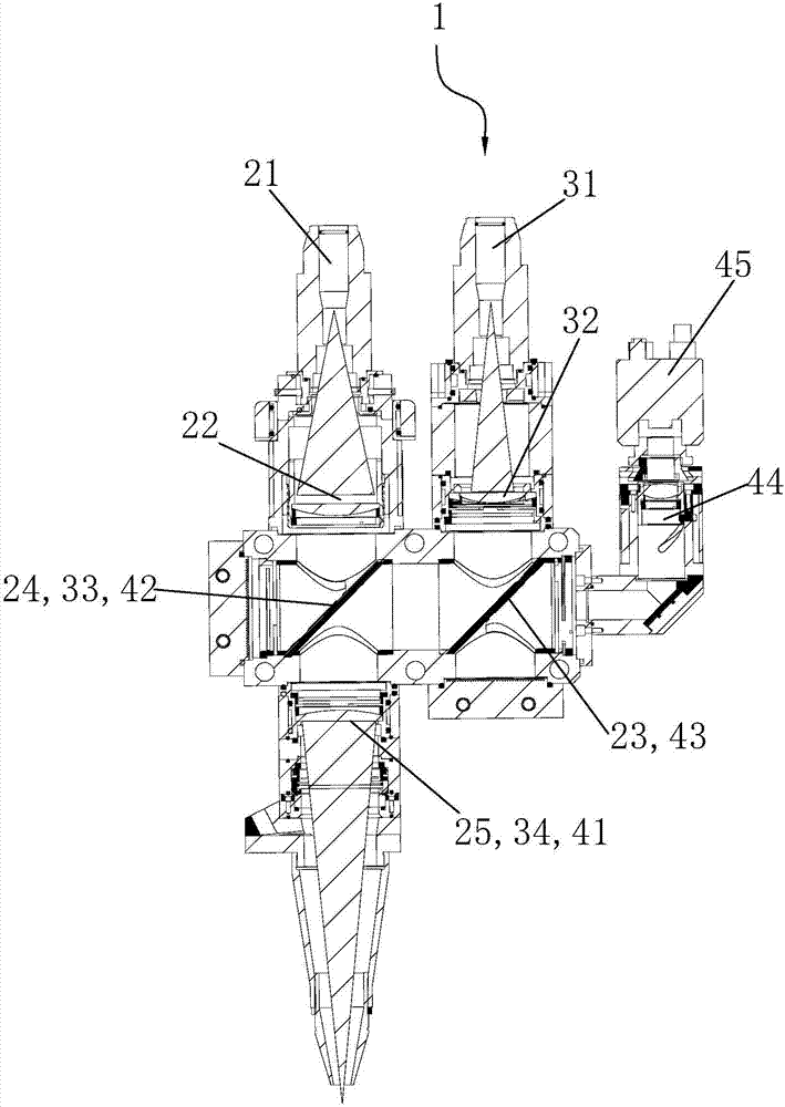
[0042] Such as image 3 , Figure 4 As shown, the basic structure, function and optical path composition of this embodiment are the same as those of Embodiment 1, the only difference lies in the placement of components on the laser head, and the basic structure of Embodiment 2 will not be described in detail here.


PUM


Abstract

The invention discloses an exiting device for laser hybrid welding. The exiting device for laser hybrid welding comprises a laser welding head, a semiconductor laser device and an optical fiber laser device, wherein the semiconductor laser device and the optical fiber laser device are respectively connected with the laser welding head; the semiconductor laser device transmits semiconductor laser; the optical fiber laser device transmits optical fiber laser; a light path of the laser welding head comprises a semiconductor light path, an optical fiber light path and a coaxial monitoring light path; a laser light beam of the semiconductor light path and a laser light beam of the optical fiber light path are superposed into a light beam for welding at a focus point of the laser welding head; a welding position is illuminated through an external light source; and light reflected by the welding position is displayed by a monitor after the welding position is imaged a coaxial monitoring light path. The technical problems that traditional welding pores are abundant, hot crack tendency is high, welding spatter is severe, welding joints are large and the like are solved. The exiting device for laser hybrid welding has the characteristics that energy utilization rate is increased, key holes are stable, the device is suitable for high-speed welding, solidification speed is reduced, the pores are also reduced, hot crack tendency is decreased, welding spatter is reduced, forming of welding joints is improved, so that a welding surface is smooth and the like.

Description

[0001] 【Technical field】 [0002] The invention relates to the technical field of laser welding, in particular to a laser composite welding emitting device. [0003] 【Background technique】 [0004] At present, laser has been widely used in industrial production, especially for metal welding, cutting, drilling, marking and surface treatment. Laser welding technology is becoming more and more important, mainly because laser welding has the characteristics of fast welding speed, easy to be guided by optical system, high precision, small deformation, and low thermal stress on the workpiece in production. Laser welding technology is gradually replacing traditional welding technology. Laser welding technology is mainly used for welding between the same metal or different metals. Since laser is a special kind of light, the welding process is closely related to the surface characteristics of metal materials. In the welding of common materials with high reflectivity such as copper an...

Claims


Application Information

Patent Timeline
IPC IPC(8): B23K26/21B23K26/064B23K26/046
CPCB23K26/046B23K26/064B23K26/21
Inventor 沈成祥周航韩金龙
Owner UNITED WINNERS LASER CO LTD
Why Eureka
Eureka Blog
Learn More