Eureka AIR delivers breakthrough ideas for toughest innovation challenges, trusted by R&D personnel around the world.

Electric drive two-gear gearbox high-speed high-performance synchronizer

A gearbox and high-performance technology, applied in the direction of mechanical drive clutches, clutches, mechanical equipment, etc., can solve the problems of complex structure, high cost, synchronous ring ablation, etc., and achieve broad market prospects, small footprint, and improved efficiency Effect

Inactive Publication Date: 2017-08-18
EASTONE AUTOMOTIVE TECH
View PDF8 Cites 2 Cited by
  • Summary
  • Abstract
  • Description
  • Claims
  • Application Information

AI Technical Summary

Problems solved by technology

However, the structure is complicated and the cost is high
If the existing synchronizer assembly used in MT or DCT is applied to an electric drive two-speed gearbox, due to the axial and radial free movement in the design of the synchronizer ring, there will be high-speed abnormal noise, while the traditional copper-based The equivalent friction diameter of the synchronous ring in the same installation space is small, and the synchronous capacity is small so that the shifting force is large. The high synchronous load of the electric drive two-speed gearbox may exceed the limit of the friction material, and problems such as synchronous ring ablation and excessive wear occur.
[0004] In addition, the retrieval of the prior art found that the Chinese invention patent application number CN201610465362.7 and the publication number CN106015382A record a high-torque synchronizer whose design idea is to use a single-cone synchronous ring and place the friction cone surface externally with the gear sleeve The inner diameter forms a friction pair to increase the friction diameter, and the synchronous ring teeth are built-in to control the synchronous process, which cannot solve the problem of synchronous ring vibration under the high-speed use of electric vehicle motors

Method used


Image

  • Electric drive two-gear gearbox high-speed high-performance synchronizer
  • Electric drive two-gear gearbox high-speed high-performance synchronizer
  • Electric drive two-gear gearbox high-speed high-performance synchronizer

Examples


Embodiment Construction

[0024] The technical solutions of the present invention will be further described in detail below in conjunction with specific embodiments.

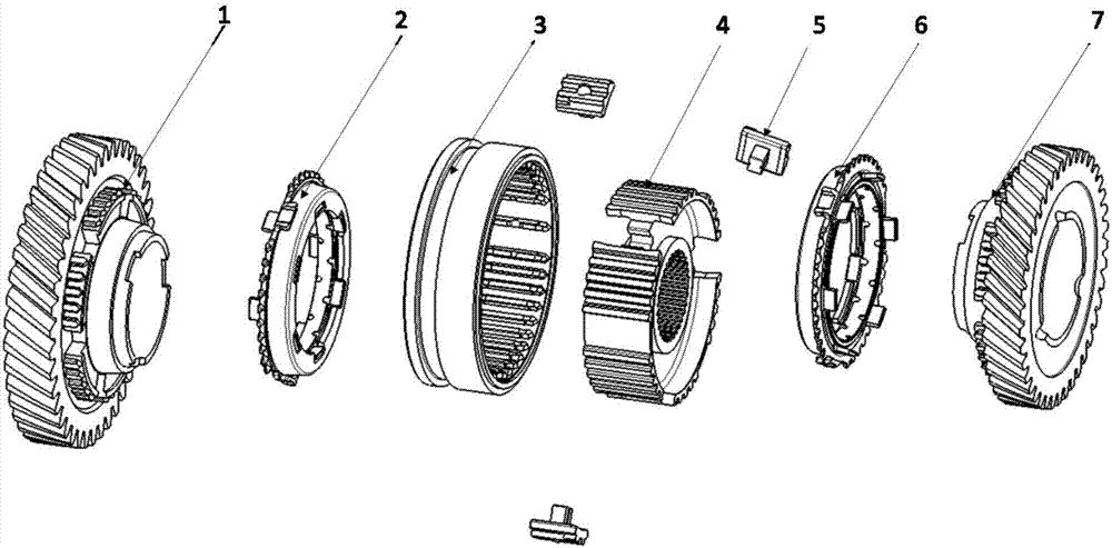
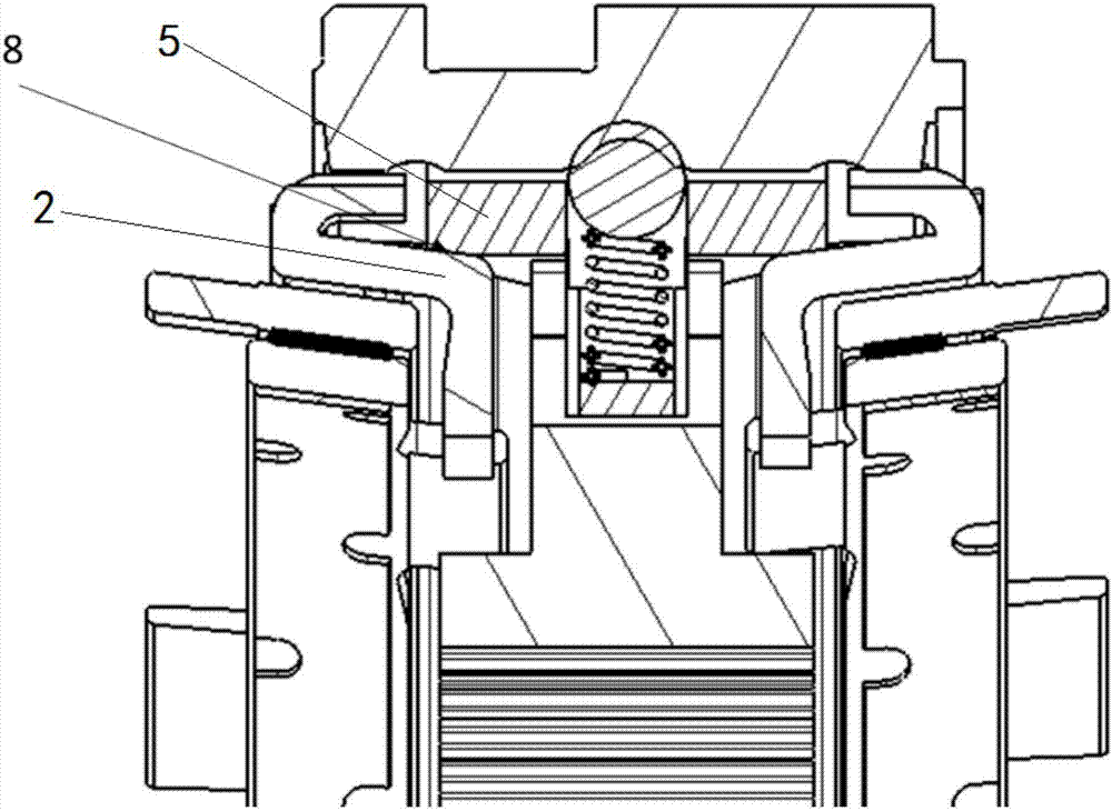
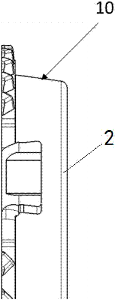
[0025] see Figure 1-6 , a high-speed, high-performance synchronizer for an electric drive two-speed gearbox, including a first-speed combined tooth 1, a first-speed synchronous ring assembly 2, a tooth sleeve 3, a gear hub 4, an anti-shake slider 5, and a second-speed synchronous ring assembly 6 and the second gear combination tooth 7; the gear hub 4 is installed on the shaft through a spline interference fit, and when the shaft rotates, the gear hub 4 is driven to rotate, and the gear hub 4 is connected with the gear sleeve 3 by spline fit, and the gear hub 4 is along the Its circumferential direction is evenly provided with a plurality of slider grooves matching with the anti-shake slider 5, the anti-shake slider 5 is installed in the slider groove, the anti-shake slider 5 is provided with a spring groove, and a spring is installed in...


PUM


Abstract

The invention discloses an electric drive two-gear gearbox high-speed high-performance synchronizer which comprises a first-gear conjunction gear, a first-gear synchronous ring assembly, a gear sleeve, a gear hub, anti-shake sliding blocks, a second-gear synchronous ring assembly and a second-gear conjunction gear. The gear hub is installed on a shaft, the gear hub and the gear sleeve are connected through spline fit, the gear hub is evenly provided with multiple sliding block grooves matched with the anti-shake sliding blocks in the circumferential direction, the anti-shake sliding blocks are installed in the sliding block grooves and provided with spring grooves, springs are installed in the spring grooves, the gear sleeve is provided with steel ball grooves corresponding to the spring grooves, steel balls are located in the steel ball grooves, and the lower portions of the steel balls extend into the spring grooves; and the first-gear synchronous ring assembly and the second-gear synchronous ring assembly are symmetrically arranged on the two sides of the gear sleeve. The requirements of the electric drive two-gear gearbox synchronizer for high-speed shaking and the high synchronous load can be effectively met, and multiple gears are achieved in the mode that the driving system efficiency is improved, energy consumption is saved and the cost is low.

Description

technical field [0001] The invention relates to the technical field of automobile synchronizers, in particular to a high-speed and high-performance synchronizer for an electric drive two-speed gearbox. Background technique [0002] In recent years, China's electric vehicles have developed rapidly, and the mass production of the electric vehicle industry has advanced rapidly. In the early stage of development, the simple matching form of motor and single-gear reducer is adopted, which basically meets the functional requirements of early mass-produced electric vehicles, mainly A0 electric vehicles. However, the further development of electric vehicles, the development of vehicle levels to A-level and B-level, puts forward higher requirements for power and high-speed economy. It is difficult to match the single-speed reducer and the motor to meet the needs of acceleration and high vehicle speed, and it is even more difficult to realize the need for the motor to work in the hig...

Claims


Application Information

Patent Timeline
Patent Type & Authority Applications(China)
IPC IPC(8): F16D23/02
CPCF16D23/02F16D23/025
Inventor 张先全简坚得杨晓枫竺春狄
Owner EASTONE AUTOMOTIVE TECH
Why Eureka
Eureka Blog
Learn More