Access network and indoor wiring optical cable

An indoor wiring and access network technology, applied in the direction of fiber mechanical structure, etc., can solve the problems of high construction and maintenance costs of optical cables, poor mechanical and temperature performance, and heavy access network optical cables, so as to achieve good anti-rodent effect and reduce construction costs. Difficulty and cost, and the effect of improving construction efficiency

Active Publication Date: 2017-08-18
FENGHUO COMM SCI & TECH CO LTD
View PDF4 Cites 1 Cited by
  • Summary
  • Abstract
  • Description
  • Claims
  • Application Information

AI Technical Summary

Problems solved by technology

In order to realize fiber optic access, it is often necessary to connect different types of access network optical cables and indoor wiring cables. The reason is that conventional access network optical cables are used for outdoor or indoor and outdoor connections, which need to have good mechanical properties and Wide operating temperature range makes conventional access network optical cables heavier
The indoor wiring type optical cable is only suitable for the laying needs of building transfer boxes, shafts and trunking, and has high requirements for flame retardancy and environmental protection performance, but its mechanical and temperature performance is not as good as that of outdoor optical cables
Due to the different structures and performances of access network optical cables and indoor wiring optical cables, there are more and more types of optical cable products, the construction is difficult and cumbersome, difficult to maintain, and the construction and maintenance costs of optical cables are high.

Method used


Image

  • Access network and indoor wiring optical cable

Examples


Embodiment Construction

[0025] The present invention will be further described in detail below in conjunction with the accompanying drawings and specific embodiments.

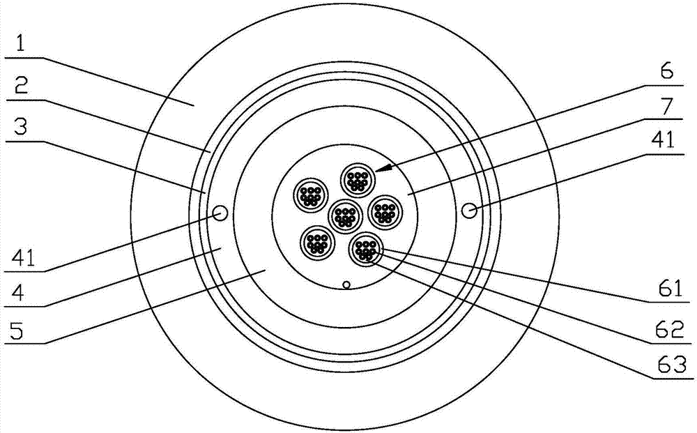
[0026] see figure 1 As shown, the embodiment of the present invention provides an access network and an indoor wiring cable. The access network and the indoor wiring cable sequentially include an outer sheath 1, an aluminum strip 2, a water blocking strip 3, a strengthening element 4, and an inner sheath from outside to inside. Set of 5 and cable core.

[0027] The outer sheath 1 is made of polyethylene, low-smoke halogen-free flame-retardant polyolefin or polyvinyl chloride. The outer sheath 1 is tightly wrapped on the aluminum strip 2, and the aluminum strip 2 and the water blocking strip 3 are arranged along the length direction of the optical cable.

[0028] The strengthening element 4 is provided with two tearing ropes 41 arranged along the length direction of the optical cable, the strengthening element 4 is made of aramid yar...


PUM


Abstract

The invention discloses an access network and indoor wiring optical cable, and relates to the technical field of communication optical cables. From the outside to the inside, the optical cable sequentially comprises an external sheath, an aluminum belt which is disposed in the length direction of the optical cable, a water-blocking tape which is disposed in the length direction of the optical cable, a reinforcing element, the interior of which is provided with two rip cords which are disposed in the length direction of the optical cable, an internal sheath, and a cable core which comprises at least one optical unit and a nonmetal reinforcing part wrapping the periphery of an optical element. The optical unit comprises a micro-beam tube and a plurality of optical fibers disposed in the micro-beam tube. The interior of the micro-beam tube is provided with a flame-retardate water-blocking element. According to the invention, the external sheath and the aluminum can be peeled off easily from the rip cords. When the optical cable is connected to a splice box or indoors, the parts outside the internal sheath can be removed, and the indoor connection and indoor wiring can be met. The application range of the optical cable is enlarged, and the construction difficulty and cost of optical cable home entry are reduced. Moreover, the construction efficiency of optical cable home entry is greatly improved.

Description

[0001] The invention relates to the technical field of communication optical cables, in particular to an access network and an indoor wiring optical cable. Background technique [0002] With the development of optical communication technology, the coverage of FTTH continues to expand. In order to realize fiber optic access to the home, it is often necessary to connect different types of access network optical cables and indoor wiring cables. The wide operating temperature range makes conventional access network optical cables heavy. The indoor wiring type optical cable is only suitable for the laying needs of building transfer boxes, shafts and trunking, and has high requirements for flame retardancy and environmental protection performance, but its mechanical and temperature performance is not as good as that of outdoor optical cables. Due to the different structures and performances of access network optical cables and indoor wiring optical cables, there are more and more t...

Claims


Application Information

Patent Timeline
Patent Type & Authority Applications(China)
IPC IPC(8): G02B6/44
CPCG02B6/443G02B6/4432G02B6/44384
Inventor 刘维思罗凡付靖宜
Owner FENGHUO COMM SCI & TECH CO LTD
Why Eureka
Try Eureka