Method for performing optical fiber laying in pipeline through liquid working medium
A liquid and optical fiber technology, applied in optical fiber/cable installation, optics, light guide, etc., can solve the problems of increasing safety hazards and not recommended to use, and achieve the effect of increasing fiber cabling distance, improving reliability, and improving reliability.
- Summary
- Abstract
- Description
- Claims
- Application Information
AI Technical Summary
Problems solved by technology
Method used
Image

Examples
Embodiment 1
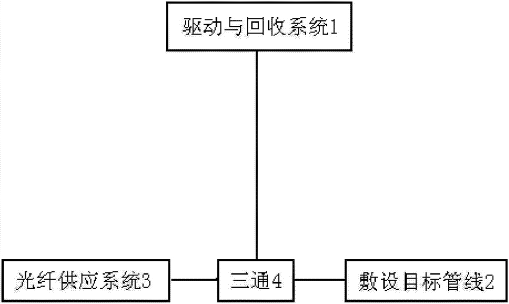
[0037] Such as figure 1 As shown, the present embodiment proposes a method for laying new optical fibers, which is applicable to optical cable processing, and it includes the following steps:
[0038] 1) Connect the tee 4 at the inlet of the laying target pipeline 2, connect one of the inlets of the tee 4 to the liquid drive and recovery system 1, connect the other inlet to the optical fiber supply system 3, and connect the outlet to the laying target pipeline 2.
[0039] 2) First turn on the liquid drive and recovery system 1, pump the liquid working medium into the laying target pipeline 2, then turn on the optical fiber supply system 3 to slowly send the new optical fiber into the tee 4, and use the dragging force of the liquid working medium to The new optical fiber is brought into the laying target pipeline 2.
[0040] 3) When the new optical fiber reaches the length to be laid, close the liquid drive and recovery system 1 and the optical fiber supply system 3 to complet...
Embodiment 2
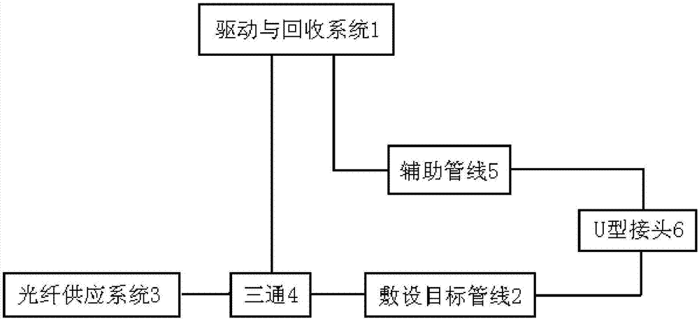
[0042] Such as figure 2 As shown, this embodiment proposes another method for laying new optical fibers, which is suitable for laying downhole optical fibers without considering the replacement of optical fibers, and includes the following steps:
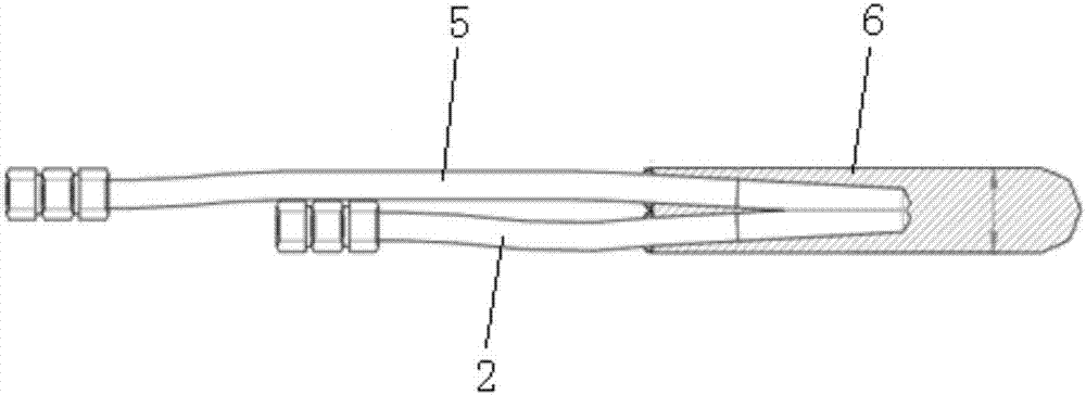
[0043] 1) There is an auxiliary pipeline 5 in the oil well to form a U-shaped structure with the laying target pipeline 2, and a U-shaped joint 6 is arranged at the U-shaped end of the two pipelines (generally the bottom end of the well for an oil field) (such as image 3 shown), to construct a liquid communication channel between the two pipelines.
[0044] 2) Connect the tee 4 at the entrance of the laying target pipeline 2, connect one of the inlets of the tee 4 to the liquid drive and recovery system 1, connect the other inlet to the optical fiber supply system 3, and connect the outlet to the laying target pipeline 2; connect the auxiliary pipeline The outlet is connected to the liquid drive and recovery system 1.
[0045] 3...
PUM
| Property | Measurement | Unit |
|---|---|---|
| Critical temperature | aaaaa | aaaaa |
| Critical pressure | aaaaa | aaaaa |
Abstract
Description
Claims
Application Information
 - R&D
- Intellectual Property
- Life Sciences
- Materials
- Tech Scout
- Unparalleled Data Quality
- Higher Quality Content
- 60% Fewer Hallucinations
Browse by: Latest US Patents, China's latest patents, Technical Efficacy Thesaurus, Application Domain, Technology Topic, Popular Technical Reports.
© 2025 PatSnap. All rights reserved.Legal|Privacy policy|Modern Slavery Act Transparency Statement|Sitemap|About US| Contact US: help@patsnap.com