LED phase-change heat radiating substrate and preparation method thereof

A heat-dissipating substrate and phase change technology, applied in electrical components, circuits, semiconductor devices, etc., can solve the problems of reducing luminous efficiency, small heat dissipation space, affecting service life, etc., to achieve excellent heat transfer performance, ensure heat dissipation performance, and ensure stability sexual effect

Pending Publication Date: 2017-08-18
SOUTH CHINA UNIV OF TECH
View PDF5 Cites 3 Cited by
  • Summary
  • Abstract
  • Description
  • Claims
  • Application Information

AI Technical Summary

Problems solved by technology

The performance of LED is closely related to the working temperature. The increase of temperature will not only reduce the luminous efficiency, but also affect the service life.
With the development of semiconductor devices in the direction of small size and high power, high-power LEDs have become the demand for light sources in many new fields. However, due to their small heat dissipation space, they have caused a fatal problem of high heat flux density. Therefore, the application of thermal control to high-power LEDs have a significant impact on the further development of
[0004] In the LED packaging process, the substrates currently used mainly include ceramic substrates, glass substrates, metal substrates, etc. Among them, metal substrates have the best heat transfer capacity, mainly copper and aluminum, which have the disadvantages of large volume and high quality, while high-power LEDs The heat flux density of the module has also exceeded the heat transfer limit of ordinary copper or aluminum materials, and the traditional method of increasing the specific surface area for heat dissipation is no longer suitable for the development of high-power LED packaging technology.

Method used


Image

  • LED phase-change heat radiating substrate and preparation method thereof
  • LED phase-change heat radiating substrate and preparation method thereof
  • LED phase-change heat radiating substrate and preparation method thereof

Examples


Embodiment 1

[0047] A method for preparing an LED phase-change heat dissipation substrate, comprising the steps of:

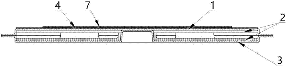
[0048] (1) Preparation of plates: Firstly, use a punching machine to punch the copper sheet according to the shape of the mold of the required upper cover plate 1 and lower cover plate 3 and cut out the upper cover plate 1 and lower cover plate 3, then place the upper cover plate Put 1 and lower cover 3 into 10 times diluted HF-223 metal cleaner for ultrasonic cleaning for 5 minutes to remove surface oil and edge burrs, and finally rinse with clean water to remove residual cleaning on the surface of upper cover 1 and lower cover 3 liquid to obtain upper cover plate 1 and lower cover plate 3;

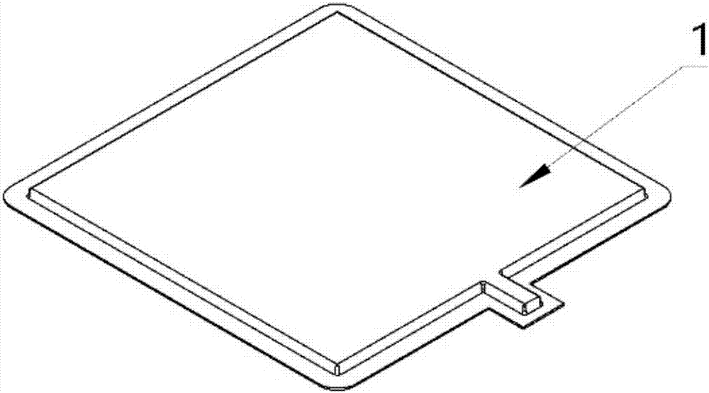
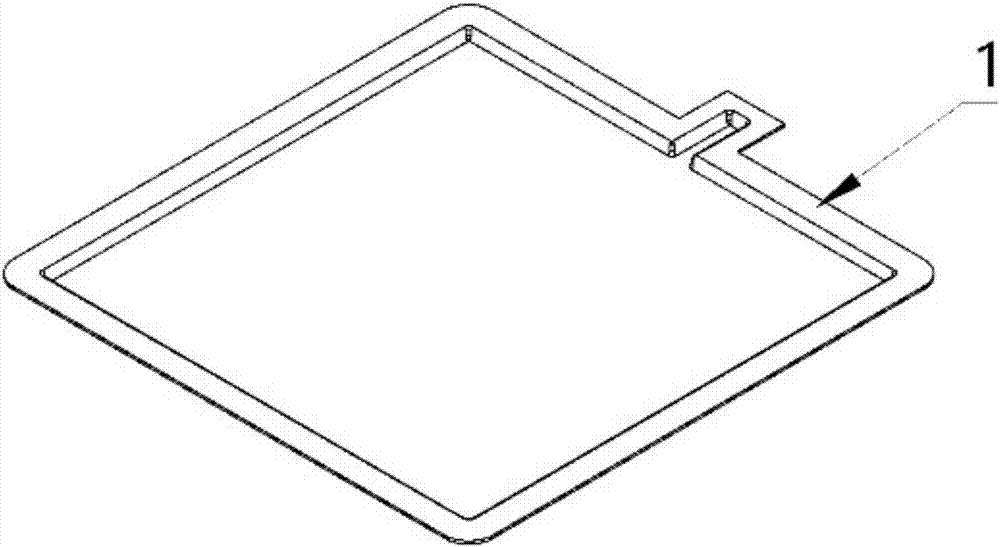
[0049] The axonometric view of the outer surface and the axonometric view of the inner surface of the upper cover plate 1 are respectively as follows figure 2 and image 3 Shown; The outer side axonometric view and the inner side axonal view of the lower cover plate 3 are respectiv...

Embodiment 2

[0055] A method for preparing an LED phase-change heat dissipation substrate, comprising the steps of:

[0056] (1) Preparation of plates: Firstly, use a punching machine to punch the copper sheet according to the shape of the mold of the required upper cover plate 1 and lower cover plate 3 and cut out the upper cover plate 1 and lower cover plate 3, then place the upper cover plate Put 1 and lower cover 3 into 10 times diluted HF-223 cleaning solution for ultrasonic cleaning for 7 minutes to remove surface oil and edge burrs, and finally rinse with clean water to remove residual cleaning solution on the surface of upper cover 1 and lower cover 3 , to obtain the upper cover plate 1 and the lower cover plate 3; then apply the insulating material nano-scale zirconia on the outer surface of the upper cover plate to form a layer of insulating adhesive layer 4 with a thickness of 0.02mm, and on the insulating adhesive layer 4 The upper cover plate finished product 1 is made on the ...

Embodiment 3

[0061] A method for preparing an LED phase-change heat dissipation substrate, comprising the steps of:

[0062] (1) Preparation of plates: Firstly, use a punching machine to punch the copper sheet according to the shape of the mold of the required upper cover plate 1 and lower cover plate 3 and cut out the upper cover plate 1 and lower cover plate 3, then place the upper cover plate Put 1 and lower cover 3 into 10 times diluted HF-223 cleaning solution for ultrasonic cleaning for 3 minutes to remove surface oil and edge burrs, and finally rinse with clean water to remove residual cleaning solution on the surface of upper cover 1 and lower cover 3 , to obtain the upper cover plate 1 and the lower cover plate 3; then apply the insulating material nano-scale zirconia on the outer surface of the upper cover plate to form a layer of insulating adhesive layer 4 with a thickness of 0.02mm, and on the insulating adhesive layer 4 The upper cover plate finished product 1 is made on the ...


PUM


Abstract

The invention discloses an LED phase-change heat radiating substrate and a preparation method thereof. The substrate comprises an upper cover plate (1), a nano wick (2), a lower cover plate (3), and liquid refrigerant filling the inside of the substrate. The nano wick (2) is sintered on the inner sides of the upper cover plate (1) and the lower cover plate (3). The upper cover plate (1) and the lower cover plate (3) are spliced together by welding. A sealed cavity is formed inside after welding. The cavity is vacuum-pumped and filled with the liquid refrigerant. The preparation method comprises the following steps: (1) preparing plates; (2) preparing a nano wick; (3) welding the plates; and (4) pouring refrigerant and carrying out packaging. The substrate is based on the principle of phase-change heat transfer. The refrigerant absorbs heat efficiently and quickly through phase change, and the heat reflux is uniformly distributed under capillary force of the nano wick after condensation. The LED phase-change heat radiating substrate has more excellent heat transfer performance, and has the characteristics of strong heat transfer ability, low weight, and small thickness.

Description

technical field [0001] The invention relates to the technical field of LED heat dissipation substrate preparation, in particular to an LED phase-change heat dissipation substrate and a preparation method thereof. Background technique [0002] With the development of LED semiconductor lighting technology, the three advantages of LED energy saving, environmental protection and long life make it gradually replace the traditional light source to become a new generation of green light source, which penetrates into people's daily life. LED light sources have been widely used in lighting, display and other fields, such as automobile headlights, miner's lamps, projectors, flat display backlights and other new fields. [0003] With the expansion and application of LED technology in different application fields, adapting to various extreme environments has become one of the requirements for the further development of LED technology, so higher requirements are put forward for the perfo...

Claims


Application Information

Patent Timeline
Patent Type & Authority Applications(China)
IPC IPC(8): H01L33/64
CPCH01L33/641H01L33/642H01L33/648H01L2933/0075
Inventor 汤勇李宗涛余彬海钟桂生袁伟余树东
Owner SOUTH CHINA UNIV OF TECH
Why Eureka
Try Eureka