Three-phase load automatic balancing system in low voltage power supply area of transformer

A three-phase load, automatic balancing technology, applied in the direction of reducing the asymmetry of the polyphase network, eliminating/reducing the asymmetry of the polyphase network, etc., can solve the problems of increasing transformer losses, three-phase unbalance of rural grids, and increasing line losses. , to achieve the effect of reducing transformer loss, avoiding heat generation and aging, and reducing line loss

Inactive Publication Date: 2017-08-18
ANHUI TELECOMM ENG
View PDF4 Cites 13 Cited by
  • Summary
  • Abstract
  • Description
  • Claims
  • Application Information

AI Technical Summary

Problems solved by technology

[0002] At present, the problem of three-phase unbalance in my country's low-voltage distribution network is very common, with high loss, many defects, and poor operation reliability, threatening the safe operation of the power grid, especially the three-phase unbalance problem in rural power grids.
The problem of unbalanced three-phase load has brought serious harm to the power system and user power supply, mainly in the following aspects: 1. Increased transformer loss; 2. Increased line loss; 3. Reduced output of distribution transformers, reducing The utilization rate of the distribution transformer is improved; 4. The transformer heats up, and even burns the transformer in severe cases; 5. It is easy to cause overvoltage and low voltage, which will affect the normal operation of electrical equipment
Although the automatic phase-changing device for low-voltage three-phase lines can achieve the purpose of self-service phase-changing, the automatic phase-changing device for low-voltage three-phase lines has large power consumption and high cost, and the communication between different branches mutual interference

Method used


Image

  • Three-phase load automatic balancing system in low voltage power supply area of transformer
  • Three-phase load automatic balancing system in low voltage power supply area of transformer
  • Three-phase load automatic balancing system in low voltage power supply area of transformer

Examples


Embodiment Construction

[0028] Below in conjunction with specific embodiment, further illustrate the present invention. These examples are only for illustrating the present invention and are not intended to limit the scope of the present invention.

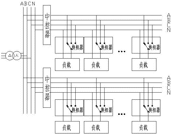
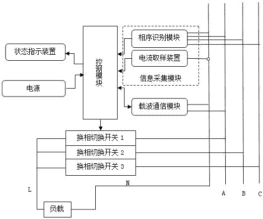
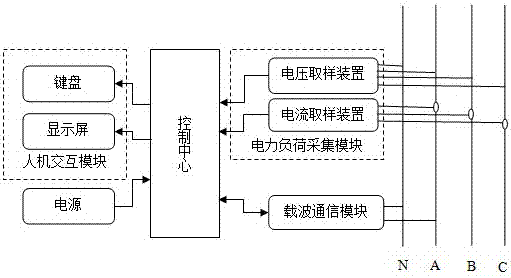
[0029] see Figure 1~3 , a three-phase load automatic balancing system for a low-voltage station area in a preferred embodiment of the present invention, including a central controller and a phase changer, the central controller is set on the main line in the station area, and the phase changer is located in the branch On the line, it is directly connected to the load. Both the central controller and the phase commutator are connected to the three-phase circuit in a three-phase four-wire system. The phase commutator monitors the current and voltage of its own load circuit in real time. size, the central controller monitors the unbalance degree of the main line in real time, and calculates the optimal leveling strategy in combination with the load size o...


PUM


Abstract

The invention discloses a three-phase load automatic balancing system in low voltage power supply area of transformer. The balancing system comprises a central controls and a phase changer. The central controller is arranged on the starting end of the branch while the phase changer is arranged at the terminal end of the branch and is connected with the load. The central controller and phase changer both adopt a three-phase four-wire method to be connected into the three-phase circuit; and communications are made between the phase changer and the central controller through power carriers. The three-phase load automatic balancing system in low voltage power supply area of transformer of the invention can effectively reduce the transformer loss and power line loss incurred from the imbalance of the three-phase load and overcomes the conditions with over-current at certain phase and low voltage at terminal end. In addition, since the system could switch phases automatically, power supply to the users does not have to be cut off. Consuming less power, the balancing system is also low in cost.

Description

technical field [0001] The invention relates to the field of electric power supply, in particular to an automatic three-phase load balancing system for a low-voltage station area transformer. Background technique [0002] At present, the problem of three-phase unbalance in my country's low-voltage distribution network is very common, with high loss, many defects, and poor operation reliability, threatening the safe operation of the power grid, especially the three-phase unbalance problem in rural power grids. The problem of unbalanced three-phase load has brought serious harm to the power system and user power supply, mainly in the following aspects: 1. Increased transformer loss; 2. Increased line loss; 3. Reduced output of distribution transformers, reducing 4. The transformer heats up, and even burns the transformer in severe cases; 5. It is easy to cause overvoltage and low voltage, which will affect the normal operation of electrical equipment. [0003] The traditional...

Claims


Application Information

Patent Timeline
Patent Type & Authority Applications(China)
IPC IPC(8): H02J3/26
CPCY02E40/50H02J3/26
Inventor 彭辰另大兵张鹏
Owner ANHUI TELECOMM ENG
Why Eureka
Try Eureka