Eureka AIR delivers breakthrough ideas for toughest innovation challenges, trusted by R&D personnel around the world.

Shock-absorbing damper with a spring plate fastened thereto, and method for the fastening of a spring plate to a shock-absorbing damper

A spring plate, damping technology, used in springs/shock absorbers, shock absorbers, springs, etc., can solve problems such as high capital expenditure, complex welding joints, etc., to achieve fast and cost-effective results

Active Publication Date: 2017-08-18
THYSSENKRUPP BILSTEIN +1
View PDF17 Cites 7 Cited by
  • Summary
  • Abstract
  • Description
  • Claims
  • Application Information

AI Technical Summary

Problems solved by technology

Producing such welded joints is however relatively complex, requiring special welding units for this purpose, the acquisition of which requires a high capital expenditure
Another inherent disadvantage of welded joints is that not all material fits can be welded to each other

Method used


Image

  • Shock-absorbing damper with a spring plate fastened thereto, and method for the fastening of a spring plate to a shock-absorbing damper
  • Shock-absorbing damper with a spring plate fastened thereto, and method for the fastening of a spring plate to a shock-absorbing damper
  • Shock-absorbing damper with a spring plate fastened thereto, and method for the fastening of a spring plate to a shock-absorbing damper

Examples


Embodiment Construction

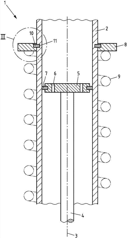
[0031] figure 1 A device 1 for damping vibrations according to the invention is shown. The device 1 comprises a damping tube 2 which is shaped like a cylinder and has a longitudinal axis 3 extending in the axial direction. Damping tube 2 is hollow and can receive liquid inside it (not in figure 1 shown in ), such as oil. The device 1 also includes a piston rod 4 at the lower end of which a piston 5 is fastened. The piston rod 4 is arranged centrally in the damping tube 2 and thus extends along the longitudinal axis 3 . The piston 5 has at least one piston valve 6 and a surrounding seal 7 . The seal 7 prevents the liquid present in the damping tube 2 from flowing through the piston 5 during its movement. Liquid can therefore only flow through the piston valve 6 so that the energy of the flow is converted into heat.

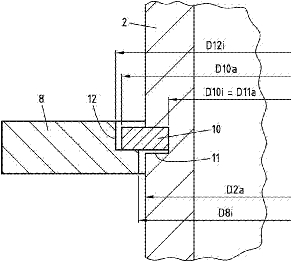
[0032] figure 1 The device 1 shown in also comprises a spring plate 8 of annular or disk-shaped design and extending around the damping tube 2 . The spring...


PUM


Abstract

A device (1) for damping vibrations is illustrated and described, which device comprises: a hollow damper tube (2), a piston rod (4) with a piston (5) fastened thereto, at least one spring plate (8), and at least one securing element (10), wherein the piston (5) is arranged within the damper tube (2), and wherein the spring plate (8) is arranged outside the damper tube (2). In order to realize a reliable connection between the spring plate (8) and the damper tube (2) in an inexpensive manner, it is proposed that the spring plate (8) be connected in both non-positively locking and positively locking fashion to the damper tube (2). The use of a device of said type in a motor vehicle, and a method for the fastening of a spring plate (8) to a damper tube (2), are also illustrated and described.

Description

technical field [0001] The invention relates to a device for damping vibrations, comprising: a hollow damping tube, a piston rod fastened with a piston, at least one spring plate and at least one fixing element, wherein the piston is arranged in the damping tube, and wherein, A spring plate is arranged on the outside of the damping tube. [0002] The invention also relates to the use of a device of this type in a motor vehicle. [0003] The invention finally relates to a method for fastening a spring plate to a damper tube. Background technique [0004] Various shock absorbers are known from the field of vehicle engineering, especially chassis engineering and its production method. The shock absorber is part of the chassis of a motor vehicle and usually interacts with a spring: the spring ensures that the wheel always returns to its original position after a deflection (Auslenkung), the shock absorber ensures that the wheel will inevitably occur due to the installation o...

Claims


Application Information

Patent Timeline
IPC IPC(8): B60G15/06F16F1/12F16F9/32
CPCB60G15/063B60G2204/1242B60G2204/12422F16F1/12F16F9/3235F16F13/007
Inventor 蒂洛·莱曼迈克尔·霍尼希
Owner THYSSENKRUPP BILSTEIN
Why Eureka
Eureka Blog
Learn More