
Variable-rigidity hydraulic three-dimensional shock isolation device and method

A technology of variable stiffness and shock isolation, which is applied in the direction of shock absorbers, springs/shock absorbers, shock absorbers, etc., can solve the problems of high cost, complex structure of combined multi-dimensional shock isolation devices, and inability to isolate vertical earthquakes

Active Publication Date: 2017-08-22
TIANJIN UNIV
View PDF6 Cites 8 Cited by
  • Summary
  • Abstract
  • Description
  • Claims
  • Application Information

AI Technical Summary

Problems solved by technology

[0005] The purpose of the present invention is to provide a novel variable stiffness hydraulic three-dimensional seismic isolation device and method which has sufficient vertical bearing capacity and vertical variable stiffness control capability, and also has suitable horizontal stiffness. Insufficiency of the seat, that is, to solve the problem that the conventional seismic isolation support cannot isolate the vertical earthquake; to solve the problems of the existing combined multi-dimensional seismic isolation device with complex structure and high cost

Method used


Image

  • Variable-rigidity hydraulic three-dimensional shock isolation device and method
  • Variable-rigidity hydraulic three-dimensional shock isolation device and method
  • Variable-rigidity hydraulic three-dimensional shock isolation device and method

Examples


Embodiment Construction

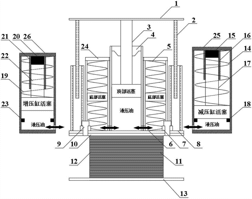
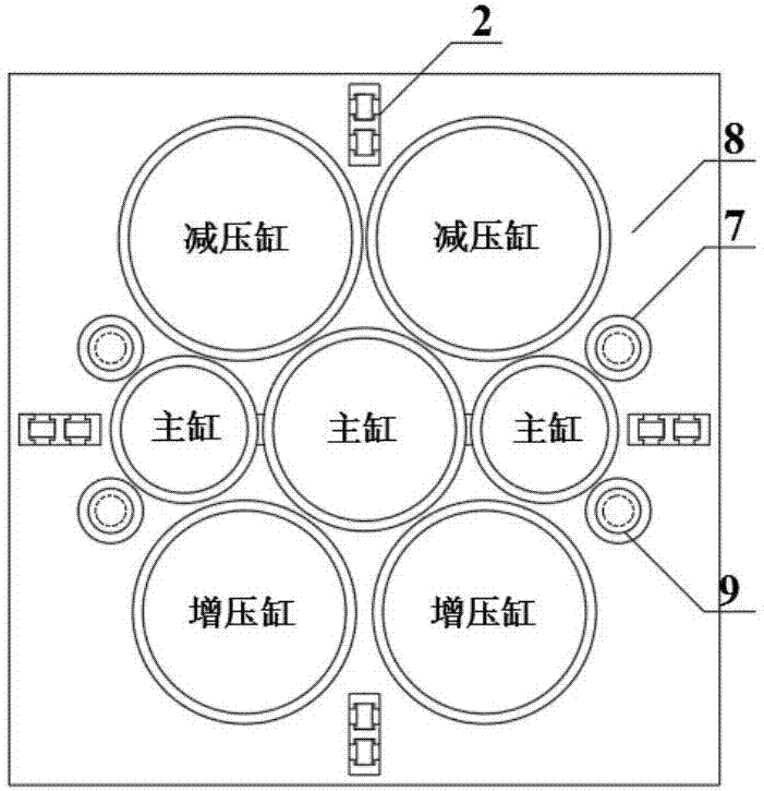
[0052] The following is an example of a three-dimensional vibration isolation device in which the master cylinder includes two bottom piston cavities and has two pressure boosting cylinders and two pressure reducing cylinders as an example: detailed description.

[0053] Taking the three-dimensional vibration isolation device in which the master cylinder includes two bottom piston cavities and two booster cylinders and two decompression cylinders to conduct three-dimensional vibration isolation in a single-layer spherical reticulated shell with a span of 50m as an example, combined with the technical solution and the attached The drawings illustrate specific embodiments of the present invention in detail so that the advantages and features of the present invention can be more readily understood by those skilled in the art.

[0054] The horizontal and vertical fundamental periods of the single-layer spherical reticulated shell with a span of 50 m are 0.318s and 0.284s, respectiv...


PUM


Abstract

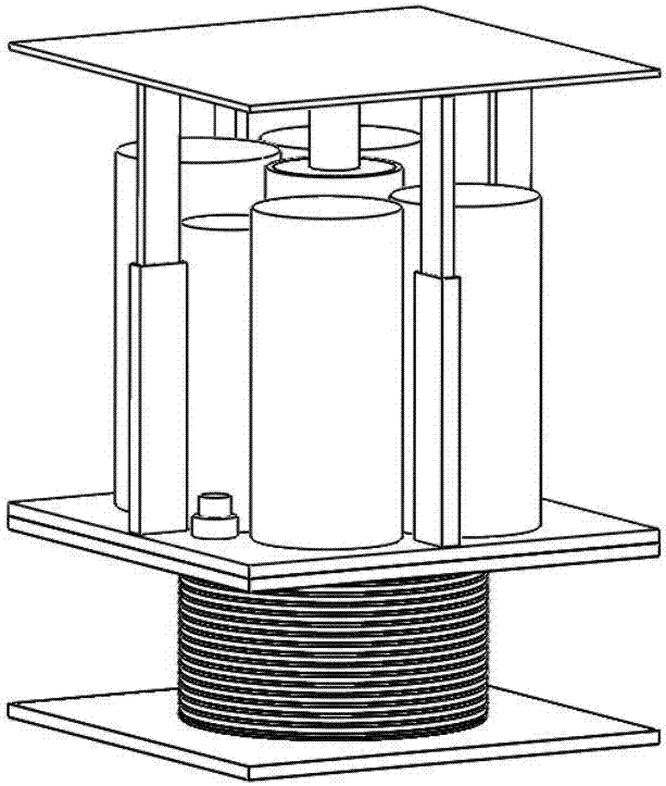
The invention relates to a variable-rigidity hydraulic three-dimensional shock isolation device and method. The variable-rigidity hydraulic three-dimensional shock isolation device comprises an upper vertical shock isolation system, a lower overlapped rubber support, a pressure reducing cylinder, a pressure increasing cylinder and a connecting component. The vertical shock isolation system comprises a vertical shock isolator upper connecting plate, a vertical guide rail, a main cylinder piston rod, a main cylinder limiting and guiding sleeve, a main cylinder bottom piston series-connection pressure spring, a main cylinder bottom piston series-connection tension spring, a vertical shock isolator lower connecting plate and a main cylinder top sealing plate. The overlapped rubber support comprises an upper connecting plate, a steel plate layer, a rubber layer and an overlapped rubber support lower connecting plate. The pressure reducing cylinder comprises a pressure reducing cylinder piston series-connection pressure spring, a pressure reducing cylinder buffering mat layer, a pressure reducing cylinder guiding sleeve, a pressure reducing cylinder piston rod, a pressure reducing cylinder supporting ring and a pressure reducing cylinder top sealing plate. The pressure increasing cylinder comprises a pressure increasing cylinder piston series-connection pressure spring, a pressure increasing cylinder buffer mat layer, a pressure increasing cylinder guiding sleeve, a pressure increasing cylinder piston rod, a pressure increasing cylinder supporting ring and a pressure increasing cylinder top sealing plate. Vertical variable-rigidity control is achieved while vertical bearing force is guaranteed, and limiting and pull-resisting measures are adopted.

Description

technical field [0001] The invention belongs to the fields of civil engineering and mechanical engineering vibration control and vibration isolation technology, and relates to a novel variable stiffness hydraulic three-dimensional vibration isolation device which has sufficient vertical bearing capacity and vertical variable stiffness control capability, and also has suitable horizontal stiffness. The method is suitable for industrial and civil buildings, bridges, subway engineering and other fields, and at the same time, it can also be used for vibration isolation (vibration) of mechanical equipment, instruments and the like. Background technique [0002] my country is located between the Pacific Rim seismic belt and the Eurasian seismic belt, and is an earthquake-prone country. How to reduce and isolate vibrations to improve the seismic performance of buildings and bridges is an important issue in the design of buildings and bridges. In the related technical field, the us...

Claims


Application Information

Patent Timeline
IPC IPC(8): F16F13/26F16F13/00
CPCF16F13/005F16F13/26
Inventor 石运东陈兆涛丁阳李忠献
Owner TIANJIN UNIV
Learn More