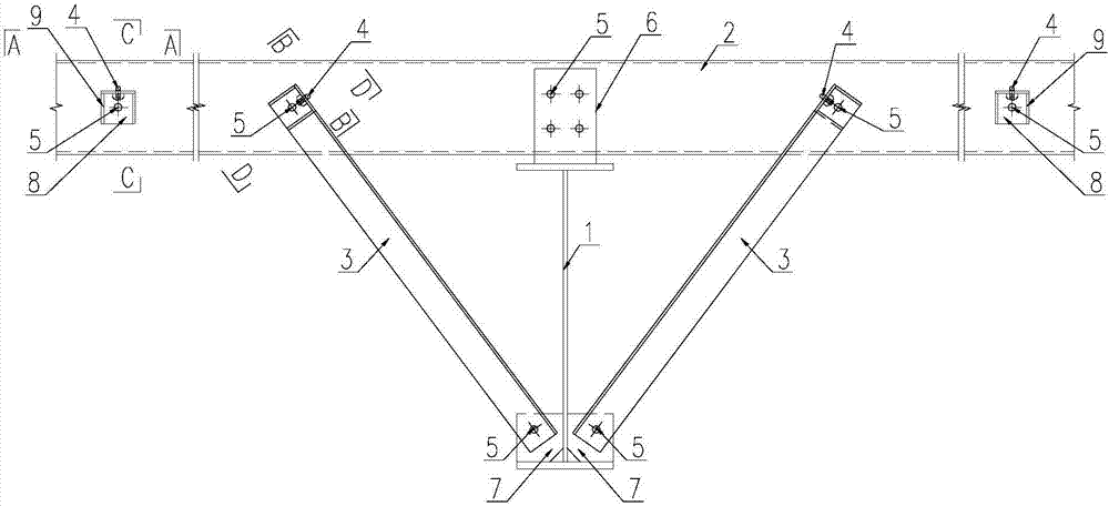
Light steel roof system with knee brace and stay as purlin support points
A technology of braces and purlins, which is applied to roofs, girders, sustainable buildings, etc., can solve the problems of weak local stiffness of purlins, reducing the effective calculation length of purlins, and relaxation of braces, so as to improve the constraints outside the plane and improve the overall space Mechanical properties, the effect of reducing the cross-section of purlins
- Summary
- Abstract
- Description
- Claims
- Application Information
AI Technical Summary
Problems solved by technology
Method used
Image

Examples
Embodiment approach
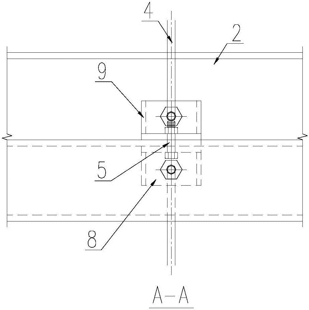
[0037] Such as Figure 4 As shown, the purlin 2 is a Z-shaped structure, the brace 4 is made of round steel, the end is bent, and a thread is provided at the bent end, and the bent end of the brace 4 passes through the brace to connect the other half of the angle steel 8 Tighten and fix the through holes on the side with nuts, so that the brace 4 is connected to the brace connection angle steel 8.
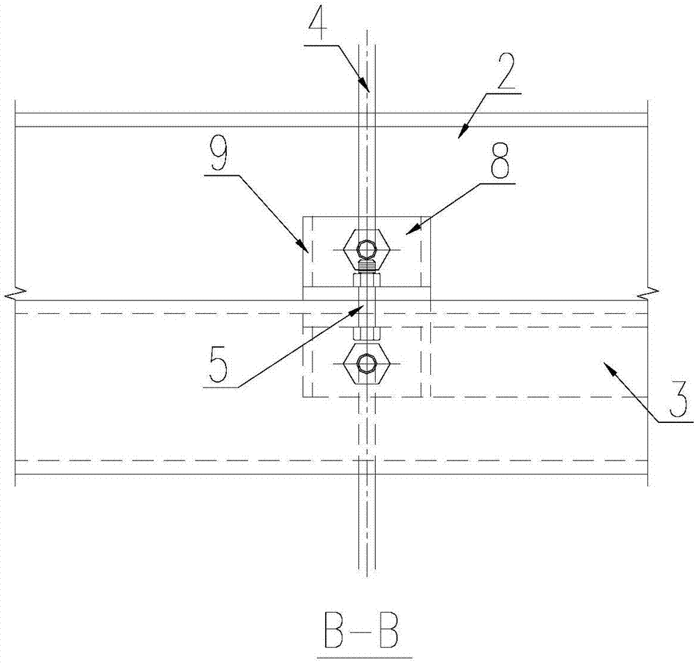
[0038] Such as Figure 5 As shown, the purlin 2 is a Z-shaped structure, and the brace 4 is made of flat steel with a through hole at the end. The through hole at the end of the brace 4 is connected to the through hole on the other half of the brace angle steel 8 and tightened with a connecting bolt 5 and a nut. Fix so that the brace 4 is connected to the brace connection angle 8.
[0039] In a specific implementation, a stiffening rib 9 for strengthening rigidity is provided between one half side and the other half side of the connecting angle steel 8 that can be stretched again...
PUM
 Abstract
Description
Claims
Application Information
 - R&D
- Intellectual Property
- Life Sciences
- Materials
- Tech Scout
- Unparalleled Data Quality
- Higher Quality Content
- 60% Fewer Hallucinations
Browse by: Latest US Patents, China's latest patents, Technical Efficacy Thesaurus, Application Domain, Technology Topic, Popular Technical Reports.
© 2025 PatSnap. All rights reserved.Legal|Privacy policy|Modern Slavery Act Transparency Statement|Sitemap|About US| Contact US: help@patsnap.com