Eureka AIR delivers breakthrough ideas for toughest innovation challenges, trusted by R&D personnel around the world.

Semiconductor laser wavelength stabilizing system and realization method

A technology for stabilizing systems and lasers, applied to semiconductor lasers, lasers, laser components, etc., can solve the problems of slow response time, low laser power density, long heat transfer path, etc., and achieve fast response speed, high control precision, and system The effect of simple structure

Pending Publication Date: 2017-08-25
XIAN YUSHI PHOTOELECTRIC SCI & TECH
View PDF4 Cites 0 Cited by
  • Summary
  • Abstract
  • Description
  • Claims
  • Application Information

AI Technical Summary

Problems solved by technology

[0004] 1) Use Volume Bragg Grating (VBG) to lock the wavelength: Although the VBG wavelength locking technology can control the temperature drift coefficient to about 0.01nm / ℃, it needs to use an optical collimator lens (such as the fast axis collimator lens FAC) when the technology is implemented. and VBG components, the overall volume is large, which limits its application in high-power side pump modules;
[0005] 2) Use DFB (Distributed Feedback) or DBR (Distributed Bragg Reflector) laser structure: the power density of DFB or DBR semiconductor laser is relatively low, and its manufacturing cost is high, making it difficult to apply to high-power pump sources;
[0006] 3) Using water cooling or TEC (Thermal-electric Cooler) to control the working temperature of the laser, etc. Maintaining the spectrally stable output of the semiconductor laser through water cooling or TEC temperature control is currently the most used method in high-power pumping, but temperature control The system generally needs to adjust the temperature of the entire pump module. Since the heat transfer path between the cold source or heat source for temperature control and the semiconductor laser is relatively long, its response time is slow; in addition, the temperature control system will increase the temperature of the entire pump module. The total volume of the Pu module
Therefore, the above scheme has not been practically promoted and applied.

Method used


Image

  • Semiconductor laser wavelength stabilizing system and realization method
  • Semiconductor laser wavelength stabilizing system and realization method

Examples


Embodiment Construction

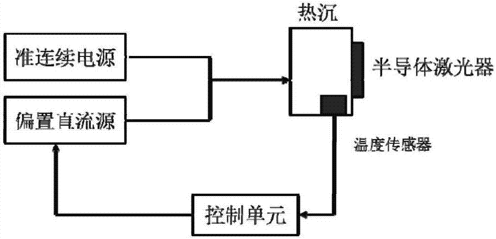
[0030] Such as figure 1 As shown, the semiconductor laser wavelength stabilization system of the present invention includes: a semiconductor laser, a heat sink, a temperature sensor, a control unit, and a driving power supply. The functional relationship between the heat sink temperature and the DC bias current is used as the control parameter, based on the control unit based on the microprocessor (specifically, a single-chip microcomputer, etc.), through the real-time detection of the heat sink temperature, according to the built-in bias current of the control unit and The relationship between the heat sink temperature adjusts the DC bias current accordingly to realize the stability of the output wavelength of the semiconductor laser.

[0031] Various packaging forms are available for semiconductor lasers, specifically conduction-cooled high-power semiconductor lasers (non-water-cooled semiconductor lasers);

[0032] The heat sink is a material with high thermal conductivit...


PUM


Abstract

The invention particularly relates to a method and a system for stabilizing a semiconductor laser wavelength. The semiconductor laser wavelength stabilizing system comprises a control unit, a driving power supply, a heat sink and a temperature sensor for detecting the temperature of the heat sink, wherein the driving power supply is a pulse current source capable of adjusting forward bias current; the semiconductor laser and the temperature sensor are both arranged on the heat sink; and the control unit is internally provided with a mathematical model for expressing the relationship between the bias current and the heat sink temperature for calculating the DC bias current value which needs to be loaded according to the detected heat sink temperature value. Through indirectly measuring the temperature of the heat sink of the semiconductor laser, stable laser wavelength output is realized through adjusting the bias DC value of the driving power supply, the structure of the system is simple, no extra heating or cooling components are needed, and no extra optical components are needed.

Description

technical field [0001] The invention belongs to the field of semiconductor laser pumping, and in particular relates to a method and system for stabilizing the wavelength of a semiconductor laser. Background technique [0002] The wavelength of semiconductor lasers has significant drift due to the influence of operating temperature and current. For example, for general 808nm or 9xx semiconductor lasers, there is a drift coefficient of 0.2-0.3nm / ℃. Wavelength drift will affect the application of semiconductor lasers. For example, when a semiconductor laser is used for solid-state laser pumping, the wavelength drift will cause a mismatch with the absorption spectrum of the solid-state laser gain medium, resulting in a decrease in pumping efficiency. [0003] Currently commonly used wavelength stabilization techniques include the following three methods, but all of them have problems. Take the pump application as an example: [0004] 1) Use Volume Bragg Grating (VBG) to lock th...

Claims


Application Information

Patent Timeline
IPC IPC(8): H01S5/068H01S5/024
CPCH01S5/02407H01S5/06804
Inventor 樊英民王警卫吴迪吴的海李小宁侯栋刘兴胜
Owner XIAN YUSHI PHOTOELECTRIC SCI & TECH
Why Eureka
Eureka Blog
Learn More