
Novel gradient thermal energy recycling system adopting two-section type sludge drying process

A sludge drying, two-stage technology, applied in dehydration/drying/thickening sludge treatment, lighting and heating equipment, steam generation, etc., can solve the waste of cooling water resources, energy failure to effectively reuse, heat waste And other issues

Pending Publication Date: 2017-08-29
苏州工业园区中法环境技术有限公司
View PDF3 Cites 5 Cited by
  • Summary
  • Abstract
  • Description
  • Claims
  • Application Information

AI Technical Summary

Problems solved by technology

At present, steam is mainly used for sludge drying in the market, and its shortcomings are: the high-temperature and high-pressure steam condensate produced by drying needs to be cooled with a large amount of cooling water resources. On the one hand, the heat of high-temperature and high-pressure steam condensate is wasted, and on the other hand On the one hand, it also wastes cooling water resources, resulting in high operating costs for sludge drying
However, there is still a problem of waste in terms of heat consumption: the saturated steam pressure used in stage I drying is higher than 3 barg, which is cooled to normal pressure by cooling water and then reused in thermal power plants. On the one hand, the energy of high-pressure condensed water cannot be effectively reused , resulting in waste of heat; on the other hand, the high-pressure condensate needs a large amount of cooling water to be cooled to normal pressure before being sent back to the thermal power plant

Method used


Image

  • Novel gradient thermal energy recycling system adopting two-section type sludge drying process

Examples


Embodiment Construction

[0015] The specific embodiments of the present invention will be further described below in conjunction with the accompanying drawings.

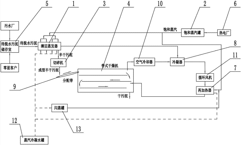
[0016] Such as figure 1 As shown, the novel thermal cascade reuse system of the two-stage sludge drying process in this embodiment includes a thin-layer evaporator 1, a saturated steam tank 2, a shredder 3 and a belt dryer 4; The sludge input end of the evaporator 1 is connected to the sludge storage room 5 to be dehydrated, the steam input port of the saturated steam tank 2 is connected to the thermal power plant 6, and the steam output port of the saturated steam tank 2 is respectively connected to the steam of the thin-layer evaporator 1 through branch pipes. Inlet and reheater 7; the waste steam outlet of the thin-layer evaporator 1 is connected to an input port of the condenser 8, and the sludge output port of the thin-layer evaporator 1 is connected to the sludge input port of the shredder 3, and the shredder 3 Chop up the sludge and ...


PUM


Abstract

The invention relates to a novel gradient thermal energy recycling system adopting a two-section type sludge drying process. The system comprises a thin-layer evaporator, a flash tank, a reheater, a belt type drier and the like, wherein the sludge input end of the thin-layer evaporator is connected with a dried sludge storage chamber; the saturation flash tank is connected with a thermal power plant; the saturation flash tank is connected with the thin-layer evaporator and the reheater through branch tubes separately; the thin-layer evaporator is connected with an input hole of a condenser; the sludge outlet hole of the thin-layer evaporator is connected with a crushing machine; a waste air outlet of the belt type drier is connected with an air cooler; the output end of the air cooler is connected with another input hole of the condenser; the output hole of the condenser is connected with a circulation fan; the output hole of the circulation fan is connected with the reheater; the reheater is used for conveying secondarily heated air to the belt type drier; and the thin-layer evaporator is connected with a steam condensed water tank through the reheater.

Description

technical field [0001] The invention relates to the field of sludge sewage treatment equipment, in particular to a sludge drying system. Background technique [0002] Sludge drying is the process of removing most of the water content from sludge through evaporation, etc., and generally refers to the use of self-evaporation facilities such as sludge drying fields (beds). At present, steam is mainly used for sludge drying in the market, and its shortcomings are: the high-temperature and high-pressure steam condensate produced by drying needs to be cooled with a large amount of cooling water resources. On the one hand, the heat of high-temperature and high-pressure steam condensate is wasted, and on the other hand On the one hand, cooling water resources are wasted, resulting in high operating costs for sludge drying. [0003] At present, a two-stage sludge drying process has appeared, and the two-stage sludge drying process reuses the waste heat steam of the thermal power pla...

Claims


Application Information

Patent Timeline
Patent Type & Authority Applications(China)
IPC IPC(8): C02F11/12F22B3/04
CPCF22B3/04C02F11/12
Inventor 张宝茸杨金牛
Owner 苏州工业园区中法环境技术有限公司
Learn More