Cooling method and system of high-temperature directly reduced iron

A cooling method and technology for reducing iron, applied in furnaces, furnace types, fluidized bed furnaces, etc., can solve the problems of reducing the iron metallization rate of pellet products, unsatisfactory pellets, and not very good effects, and avoid iron Re-oxidized or pellet burst, low cost of construction and operation, avoids the effect of iron being oxidized by water

Inactive Publication Date: 2011-09-14
CISDI ENG CO LTD
View PDF4 Cites 8 Cited by
  • Summary
  • Abstract
  • Description
  • Claims
  • Application Information

AI Technical Summary

Problems solved by technology

These two modes of cooling have their disadvantages: Although the cooling speed of the former cooling mode is fast, the high-temperature pellets directly enter the water pool, which is easy to cause bursting, so that the pellets cannot meet the requirements of being used as raw materials for blast furnaces; In addition, the amount of iron tetroxide produced by the oxidation of iron by water is relatively large, which reduces the iron metallization rate of the pellet product, and makes the energy consumed by the oxidized iron heated and reduced in the rotary hearth furnace be wasted in vain ; Although the latter cooling mode will not oxidize the pellets, because it adopts the mode of nitrogen protection inside and cooling outside, the heat of the pellets must be transferred through the gas, and the heat transfer effect of the gas is not very good, so in order to To achieve the required cooling temperature, the length of the cooling equipment must be increased, which makes the investment cost of the cooling system higher, and at the same time, the amount of protective gas and cooling water will be relatively large

Method used


Image

  • Cooling method and system of high-temperature directly reduced iron
  • Cooling method and system of high-temperature directly reduced iron

Examples


Embodiment Construction

[0022] Hereinafter, preferred embodiments of the present invention will be described in detail with reference to the accompanying drawings.

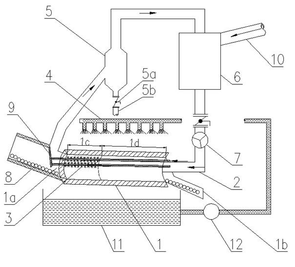
[0023] In the high-temperature direct-reduced iron cooling method of the present invention, under the protection of protective gas, the high-temperature direct-reduced iron is directly sprayed with water mist to cool to above 620°C, and then the outer wall of the direct-reduced iron container is sprayed with water or passed through for cooling, thereby Indirect cooling of direct reduced iron. According to the chemical thermodynamics of the reaction between iron and water vapor, when the temperature is higher than 620 ° C, the Gibbs free energy of the reaction between iron and water (to generate ferric oxide and hydrogen or to generate ferrous oxide and hydrogen) is greater than 0, so it is not A reaction will occur; therefore, first directly cool the high-temperature direct reduced iron, use the direct contact heat exchange between the d...


PUM


Abstract

The invention discloses a cooling method and a system of high-temperature directly reduced iron. Under the protection of protective gas, firstly, water mist is directly sprayed to the high-temperature directly reduced iron so that the high-temperature directly reduced iron cools over 620 DEG C, and then water is sprayed or fed to the outer wall of the vessel of the directly reduced iron for cooling purpose, thus indirectly cooling the directly reduced iron. By analyzing the chemical reaction property of iron and steam, the method concludes that the iron above 620 DEG C does not react with steam. Therefore, the method can realize rapid cooling effect by first directly cooling the high-temperature directly reduced iron, and also avoid oxidation of iron by water. Then, the directly reduced iron is cooled to required temperature by a regular indirect cooling method. At the time, yet without direct contact of water with directly reduced iron, the oxidation of iron by water is avoided. The whole cooling process proceeds under the protection of protective gas, thus preventing iron from being oxidized by air. Compared with the method of totally indirect cooling, the method of first direct cooling and second indirect cooling is higher in cooling efficiency, and can also prevent iron from being oxidized for a second time or balls from bursting.

Description

technical field [0001] The invention belongs to the technical field of iron and steel metallurgy, and in particular relates to a cooling method and system for high-temperature direct reduced iron. Background technique [0002] Rotary hearth furnace treatment of iron and steel enterprise dust sludge and direct reduction of iron ore mainly includes the fastmelt process jointly developed by Japan's Kobe Steel and the American Midland Company and the Inmetco process developed by Canada's International Nickel Corporation. Their processes are similar. First, the raw materials including iron and steel plant dust or concentrate powder, coal powder, binder, etc. are mixed through a mixer, and then pelletized by a pelletizer and dried to preheat the raw pellets. Enter the rotary hearth furnace to carry out reduction reaction at high temperature, and reduce the iron oxide pellets into direct reduced iron pellets; The cooling protection system is used to cool the product to be used as ...

Claims


Application Information

Patent Timeline
Patent Type & Authority Applications(China)
IPC IPC(8): C21B13/00
Inventor 胡斐雍海泉
Owner CISDI ENG CO LTD
Why Eureka
Try Eureka