Spinning and dyeing spiral dehydration device
A technology of spiral dehydration and textile printing and dyeing, which is applied in the direction of processing textile material equipment configuration, processing textile material carrier, processing textile material untwisting device, etc. It can solve the problems of increasing textile dehydration time and running for a long time, so as to avoid waste water splashing , to ensure unobstructed, thorough dehydration effect
- Summary
- Abstract
- Description
- Claims
- Application Information
AI Technical Summary
Problems solved by technology
Method used
Image

Examples
Embodiment 1
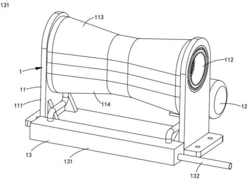
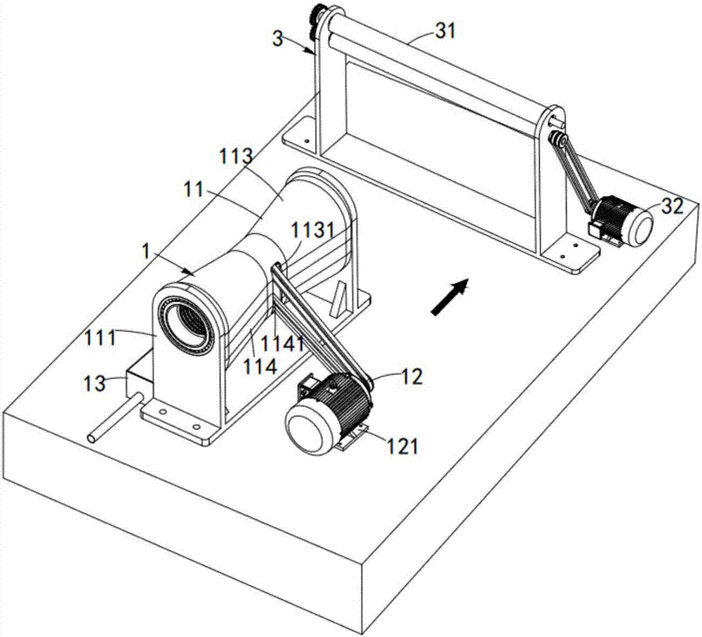
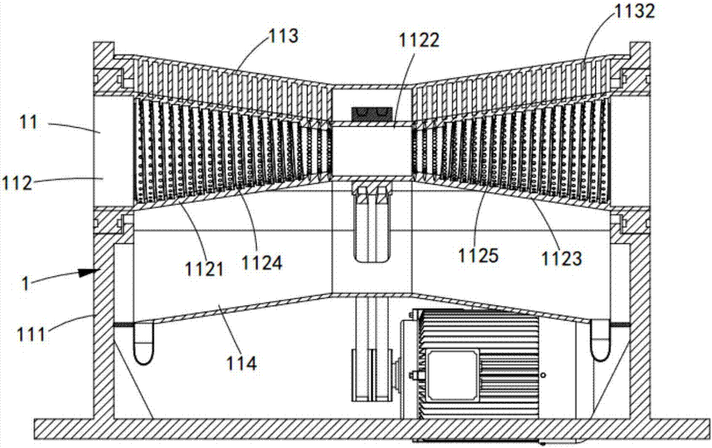
[0052] like figure 1 As shown, a textile printing and dyeing spiral dehydration equipment, including a spiral dehydrator 1 and a tractor 3 from front to back, is characterized in that the spiral dehydrator 1 is arranged on the front side of the tractor 3, which includes a spiral dehydrator Mechanism 11, a first driving mechanism 12 and a waste water diversion mechanism 13, the first driving mechanism 12 is arranged on one side of the spiral dehydration mechanism 11, which drives the spiral dehydration mechanism 12 to dehydrate the textiles that have been printed and dyed. The waste water diversion mechanism 13 is arranged on the other side of the spiral dehydration mechanism 11, which guides and collects the waste water detached from the spiral dehydration mechanism 12;
[0053] The traction machine 3 includes a traction mechanism 31 and a third drive mechanism 32, the third drive mechanism 32 is arranged on one side of the traction mechanism 31, and it drives the traction mec...
Embodiment approach
[0064] like Figure 10 Shown as a preferred embodiment, the wastewater diversion mechanism 13 includes a sump 131 and a drainage pipe 132, the sump 131 is set corresponding to the first drive mechanism 12, and it is located on the side of the dehydration frame 111. The other side, and it communicates with the lower water collecting tank 114;
[0065] The drainage pipe 132 is arranged on one side of the sump 131 and communicated with the sump 131 . The drainage pipe 132 is used to drain the waste water in the sump 131 into the waste water pool.
[0066] It should be noted that the water collection tank 131 is sealed. Since the textiles are dyed and other chemicals are added during the printing and dyeing process, the above chemicals will produce their own irritating odors, which will seriously damage the respiratory system of the printing and dyeing workers. In the setting of the device, the sealing design should be adopted as much as possible to reduce the volatilization of i...
Embodiment 2
[0074] Figure 13 It is a structural schematic diagram of Embodiment 2 of a textile printing and dyeing spiral dehydration equipment of the present invention; as Figure 13 As shown, the components that are the same as or corresponding to those in the first embodiment are marked with the corresponding reference numerals in the first embodiment. For the sake of simplicity, only the differences from the first embodiment will be described below. This embodiment two and figure 1 The difference of the shown embodiment one is:
[0075] like Figure 13 and Figure 14 As shown, a textile printing and dyeing screw dehydration equipment also includes a horizontal pre-opener 2 arranged between the screw dehydrator 1 and the tractor 3, and the horizontal pre-opener 2 includes a pre-opener mechanism 21 and The second driving mechanism 22, the second driving mechanism 22 is arranged at the lower part of the pre-opening mechanism 21, which drives the pre-opening mechanism 21 to perform p...
PUM
 Abstract
Description
Claims
Application Information
 - R&D
- Intellectual Property
- Life Sciences
- Materials
- Tech Scout
- Unparalleled Data Quality
- Higher Quality Content
- 60% Fewer Hallucinations
Browse by: Latest US Patents, China's latest patents, Technical Efficacy Thesaurus, Application Domain, Technology Topic, Popular Technical Reports.
© 2025 PatSnap. All rights reserved.Legal|Privacy policy|Modern Slavery Act Transparency Statement|Sitemap|About US| Contact US: help@patsnap.com