Roadbed protective system in debris flow gully and implementation method for roadbed protective system

A technology of debris flow ditch and protection system, applied in dikes, road bottom, coastline protection, etc., can solve problems such as reducing maintenance costs and blockage risks during tunnel drainage, uneven stress on drainage structures, and long drainage tunnel lines. , to achieve the effect of low maintenance cost and blockage risk, ensuring stability and durability, and low engineering investment

Inactive Publication Date: 2017-08-29
CHANGJIANG SURVEY PLANNING DESIGN & RES
View PDF5 Cites 7 Cited by
  • Summary
  • Abstract
  • Description
  • Claims
  • Application Information

AI Technical Summary

Problems solved by technology

The disadvantages of this method are: the route of the drainage tunnel is long, the construction period is long, and the project investment is large; in addition, a complex layered drainage structure needs to be built at the entrance of the tunnel to reduce maintenance costs and risk of blockage during tunnel drainage
[0004] For the high-fill road section in the valley, the problem of uneven settlement of the subgrade is more prominent, and the force of the drainage structure is uneven. The traditional masonry culvert or concrete culvert is easily cracked. , the drainage structure is easily damaged, and eventually the roadbed is washed away

Method used


Image

  • Roadbed protective system in debris flow gully and implementation method for roadbed protective system
  • Roadbed protective system in debris flow gully and implementation method for roadbed protective system
  • Roadbed protective system in debris flow gully and implementation method for roadbed protective system

Examples


Embodiment approach

[0041] A method for implementing a subgrade protection system in a debris flow ditch, comprising the following steps;

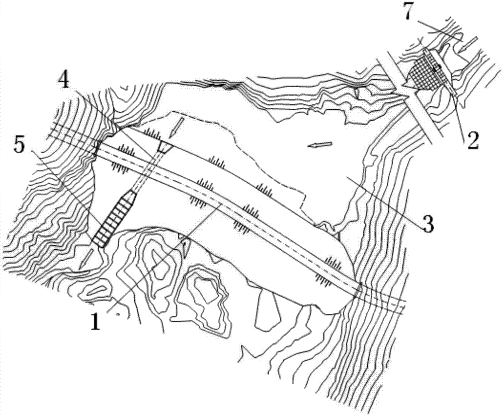
[0042] ①. Determine the formation area and circulation area of ​​the debris flow through on-site investigation of the quantity and distribution of loose materials in the debris flow ditch;

[0043] 2. In the debris flow formation area and circulation area determined in step 1., select a location with good geological conditions and a large storage capacity in front of the dam as the dam site of the retaining dam 2, and the number of the dam sites of the retaining dam 2 is based on loose The distribution of substances is determined;

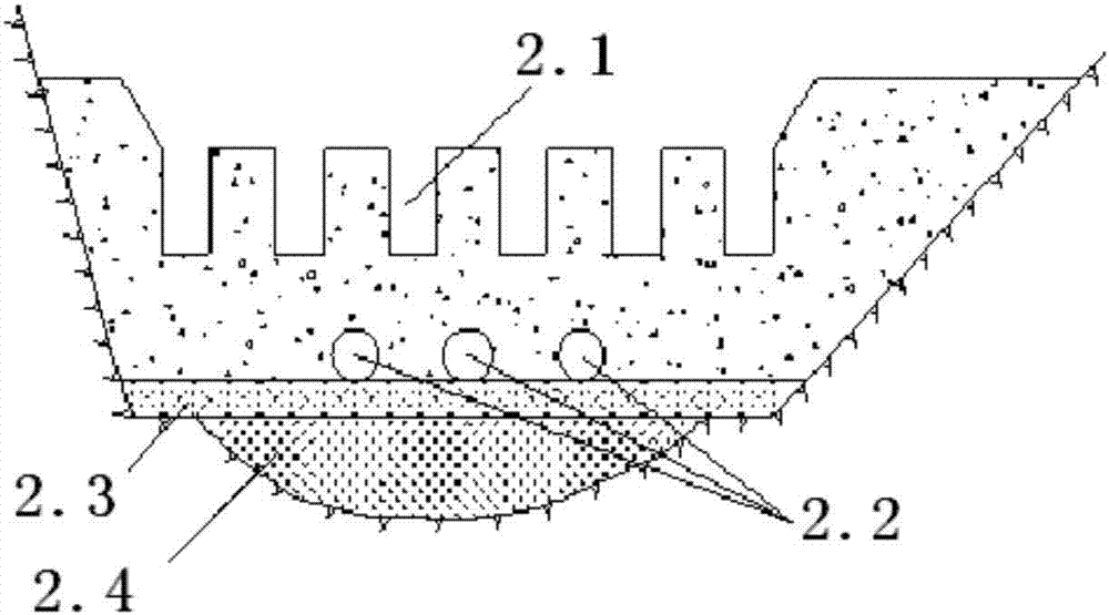
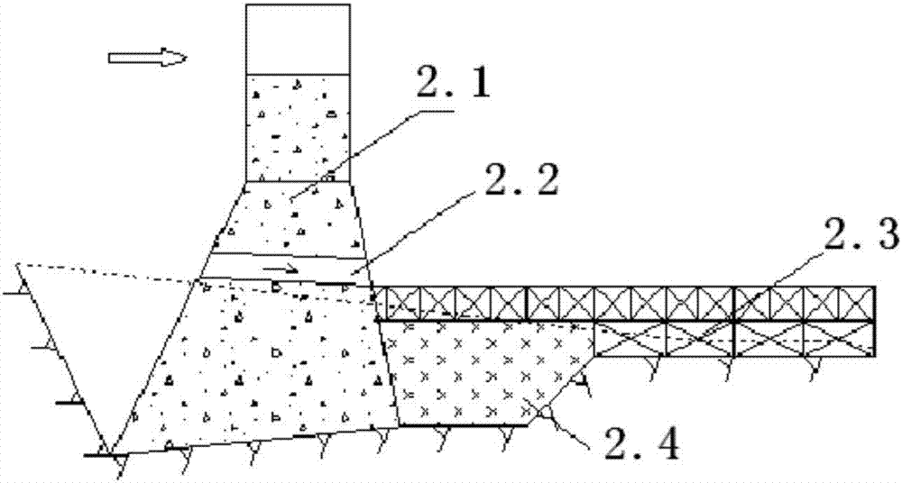
[0044] 3. Excavate the foundation of the retaining dam 2 at the dam site determined in step 2 until the anti-sliding stability requirements of the dam body are met, and the bank slope of the abutment is excavated into grooves so that the dam body of the retaining dam 2 is embedded in the bank slope bedrock;

[0045] 4. The retai...


PUM


Abstract

The invention discloses a roadbed protective system in a debris flow gully and an implementation method for the roadbed protective system, and the roadbed protective system is arranged along the debris flow gully (7). The roadbed protective system comprises a blocking dam (2), a stop and deposit field (3), a drainage guide culvert (4) and an energy dissipation slot (5), wherein the blocking dam (2) is positioned in an upstream channel of the debris flow gully (7); the stop and deposit field (3) is positioned between the blocking dam (2) and a roadbed filling body (1) arranged at the downstream; an inlet of the drainage guide culvert (4) is mutually jointed with the stop and deposit field (3); the drainage guide culvert (4) transversely penetrates through the roadbed filling body (1); and a downstream slope surface at the outlet of the drainage guide culvert (4) is jointed with the energy dissipation slot (5). The roadbed protective system overcomes the defects that a drainage guide structure in the prior art is easily damaged and finally causes the roadbed to be destroyed by rush of water, and has the advantages of reducing scouring, on the both sides of the channel, of debris flow, and prevents most of rock blocks from discharging.

Description

Background technique [0001] The invention relates to the technical field of highway mud-rock flow prevention and control, and more specifically relates to a roadbed protection system in a mud-rock flow ditch and an implementation method. Background technique [0002] When mountain roads shuttle through the mountains, they often encounter debris flow valleys, where the valleys are deep and the slopes are steep, and the runoff in the rainy season is large and accompanied by debris flow disasters. There are mainly two ways to cross the road section of the debris flow ditch: 1. Bridge; 2. Subgrade filling body. Due to the characteristics of high speed, high energy, and large particle impact of debris flow, if a bridge is used, its structure is complicated and the cost is high. When debris flow passes in the ditch, it will pose a huge threat to the bridge structure. The subgrade filling body has a simple structure and can use road excavation materials, and the cost is relative...

Claims


Application Information

Patent Timeline
Patent Type & Authority Applications(China)
IPC IPC(8): E02B3/00E02B7/10E02B3/10E01F5/00E02B5/00
CPCE01F5/005E02B3/00E02B3/10E02B5/00E02B7/10Y02A10/11
Inventor 刘波牛运华范五一王曙东王永玲李婧石志超
Owner CHANGJIANG SURVEY PLANNING DESIGN & RES
Why Eureka
Try Eureka