
Welding wire box with moisture protection

A technology of welding wire box and welding wire, which is applied in the direction of providing/exhausting shielding gas devices, welding equipment, manufacturing tools, etc., can solve problems such as high cost, escape, and increase in cost

Active Publication Date: 2019-08-23
FRONIUS INTERNATIONAL GMBH
View PDF7 Cites 0 Cited by
  • Summary
  • Abstract
  • Description
  • Claims
  • Application Information

AI Technical Summary

Problems solved by technology

Disadvantageous in this method is that there is no provision for active removal of the moisture introduced when the welding wire is placed in the system
Additionally, the hermetic seal makes handling the overall system significantly more difficult, increases cost and reduces flexibility
Gas cylinders are also proposed for supplying inert gas or dry air, which are disadvantageous in terms of cost and logistics
The use of pressure regulators for loading the overall system with overpressure has the additional disadvantage that in the event of leaks a very high mass flow of inert gas can escape from the system, which in turn leads to high costs
This not only increases the outlay for the welding process but also leads to higher costs

Method used


Image

  • Welding wire box with moisture protection
  • Welding wire box with moisture protection
  • Welding wire box with moisture protection

Examples


Embodiment Construction

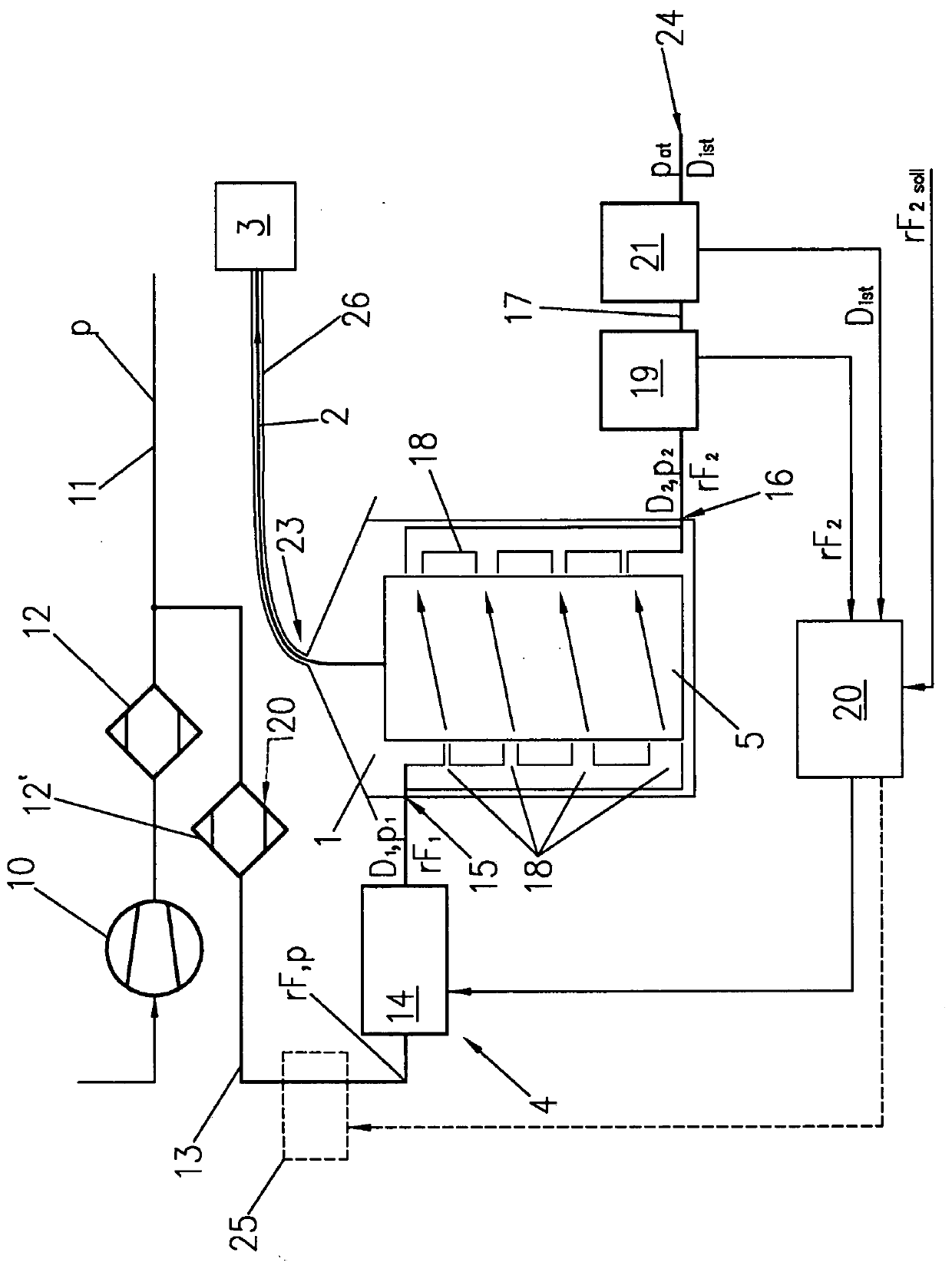
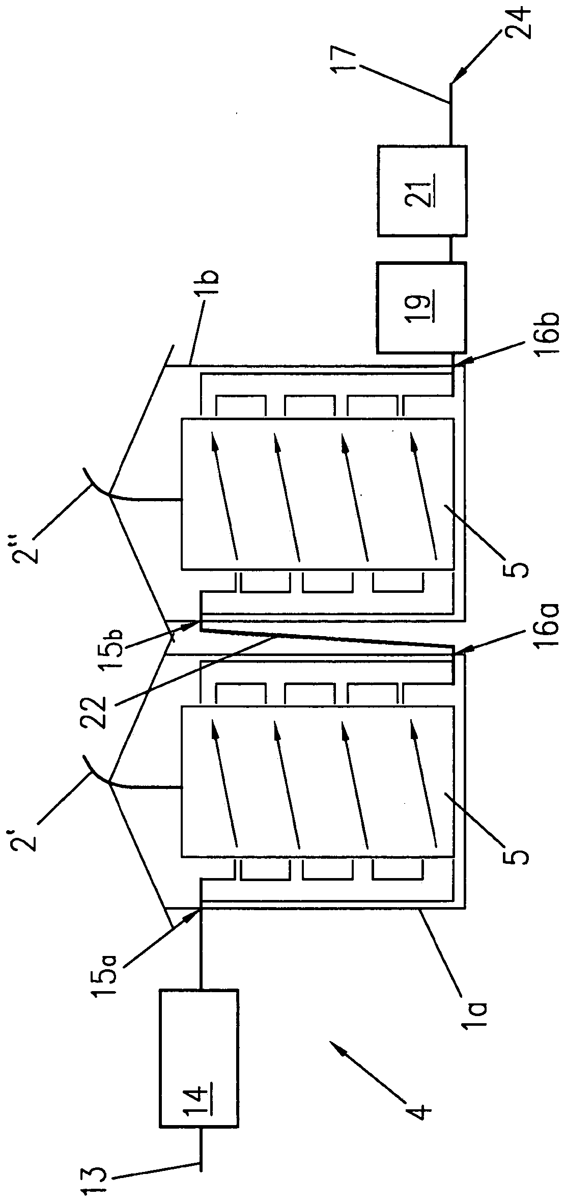
[0021] figure 1 A welding wire box 1 is shown, in which a welding wire 2 is placed in a sufficiently known manner, from which it is removed by a welding process 3 not shown in detail here and used for welding. Welding devices with auxiliary devices required for the welding process 3 , such as a shielding gas supply, are sufficiently known and are not shown or described in detail here. The feed unit for feeding the welding wire 2 can be arranged in the welding wire box 1 , but also in the welding device itself and / or in the welding torch. The welding wire 2 is usually placed in the welding wire box 1 in the form of a welding wire coil 5, as in figure 1 shown in . In order to protect the welding wire 2 against the moisture contained in the ambient air, a guard 4 is provided, which will be described in detail below.

[0022] Ambient air is compressed by a compressor 10 and scavenging air is produced at a pressure p and is made available via a compressed air line 11 . In thi...


PUM


Abstract

In order to easily and safely reduce moisture accumulation on the welding wire (2, 2', 2") arranged in the wire box (1, 1a, 1b) or to remove existing moisture, the following settings are made: The flow rate (D 1 ) is regulated by means of a flow regulating unit (14), the purge air is supplied to the flow regulating unit (14) at a first pressure (p) and at the purge air outlet (24) of the welding wire box (1, 1a, 1b) at a Three pressures (p at ) is derived, and the adjusted flow rate (D 1 ), the third pressure (p at ) and the flow resistance between the scavenging air supply (15) and the scavenging air outlet (24) results in a second pressure on the scavenging air supply (15) (p 1 ), the second pressure is less than the first pressure (p), wherein, by stepping down from the first pressure (p) to the second pressure (p 1 ) to reduce the relative humidity of the scavenging air (rF 1 ).

Description

technical field [0001] The invention relates to a welding wire box for containing welding wire, which has a protective device against moisture, wherein a purge air supply and a purge air outlet are arranged on the welding wire box for supplying dry purge air The scavenging air supply line leads into the scavenging air supply part, the scavenging air outlet part has a scavenging air outlet for leading the scavenging air out of the welding wire box, and relates to a protective A method of protecting welding wire from moisture in a wire box. Background technique [0002] A known problem in shielding gas welding of specified materials, especially aluminum, titanium or other highly reactive metals, is so-called hydrogen porosity. In this case, due to the hydrogen in the area of ​​the welding point, there are pores in the weld seam which reduce the quality of the weld seam or even make it unusable. Hydrogen is often introduced, for example, through the supplied weld seam, since ...

Claims


Application Information

Patent Timeline
Patent Type & Authority Patents(China)
IPC IPC(8): B23K9/133B23K9/32
CPCB23K9/133B23K9/32F24F11/72F24F2110/20F24F11/30B23K35/38B01D53/263B23K9/164B23K9/325
Inventor H·恩斯布鲁纳
Owner FRONIUS INTERNATIONAL GMBH
Learn More