Measurement of ion concentration in presence of organics
A technology for metal ion concentration and organic compounds, which can be used in measuring devices, immunoassays, biomaterial analysis, etc., and can solve problems such as mass transfer contribution and resistance drop
- Summary
- Abstract
- Description
- Claims
- Application Information
AI Technical Summary
Problems solved by technology
Method used
Image
Examples
example
[0206] Table 1
[0207]
[0208]
[0209] Table 2 below illustrates some examples of standard reduction potentials for some metals:
[0210] Table 2
[0211]
[0212]
[0213]
[0214] Any of the oxidation or reduction potentials listed in Tables 1 and 2 above may be considered in determining the voltage range for potential cycling to measure the concentration of a particular metal ion.
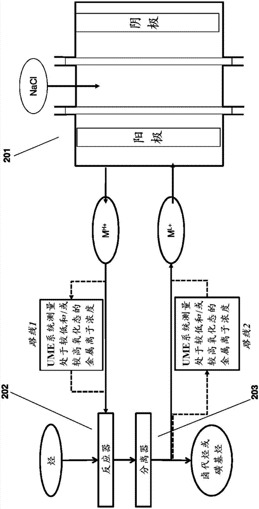
[0215] In some embodiments of the methods and systems provided herein, the metal ion is copper, or the metal ion is a metal ion of a metal halide, such as copper halide or copper chloride. In some embodiments, the one or more organic compounds include chlorohydrin and / or EDC.
[0216] In some embodiments, cleaning the UME surface to avoid deposition of one or more organic compounds by passing a gas over the UME surface comprises hydrogen sparging, oxygen sparging, or chlorine sparging on the UME surface. This method can be used in conjunction with the application of potentia...
Embodiment 1
[0265] Application of two sets of potential cycles for measuring metal ion concentrations in the presence of organic matter
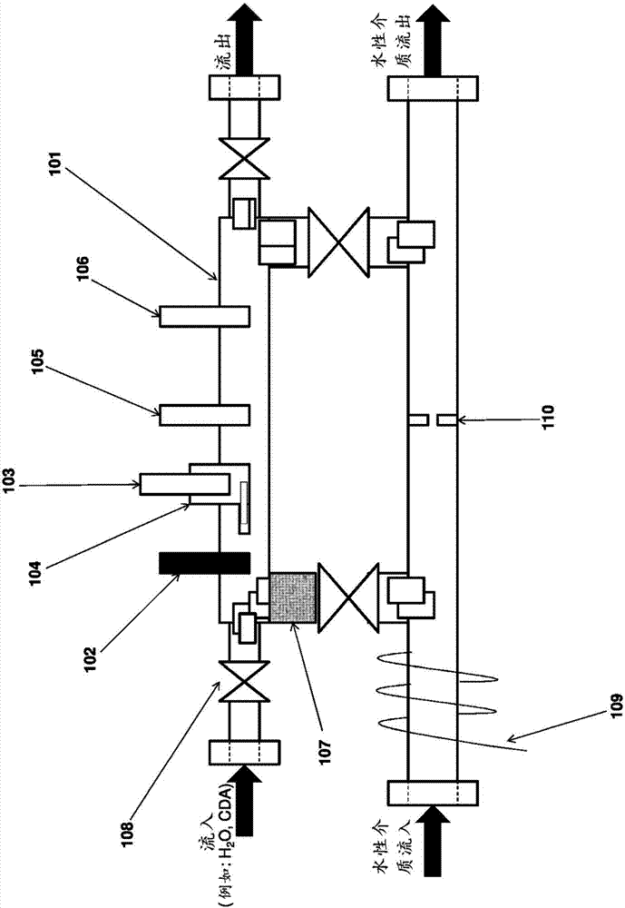
[0266] In this experiment, a three-electrode system was employed, comprising a 25 μm platinum microelectrode (eg from CH Instruments), an Ag|AgCl reference electrode and a salt bridge (eg from Gamry), and a platinum wire. The lower half of the UME cell is immersed in a water bath at a temperature of approximately 90 °C. The flow of copper is controlled by a peristaltic pump. In some experiments, flow through the UME cell was controlled by opening and closing valves on either side of the UME cell.
[0267] For the first set of potential cycles, the potential applied to the electrodes was swept from 0.45 V to 2 V at 0.5 V / s for 10 cycles. from Cu(I)Cl reduction potential and O 2 / Cl 2 The precipitation potential determines the potential window. Below 0.45 V, Cu(I) can be reduced to metallic copper and deposited on the UME surface, which is avoided. ...
Embodiment 2
[0270] Application of Potential Cycling for Measuring Metal Ion Concentration in the Presence of Organic Matter
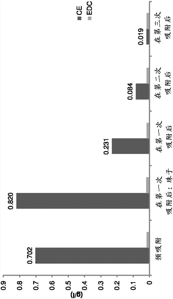
[0271] Pre-adsorption with polystyrene beads: In a laboratory setting, 100 g of polystyrene beads were added to 500 ml of copper solution (5M CuCl 2 , 1M CuCl and 2.5M NaCl). After 15 minutes, the beads were filtered off and fresh beads (100 g) were added to the solution. After 3 times, the CE level in the solution dropped to 20ppm or less (as measured by gas chromatography), as Figure 3A shown in . The copper solution was then run through a UME cell, and compared to the constant decay without adsorption with polystyrene beads, the copper(I) concentration (as currently measured) was found to be stable, as Figure 3B shown in .
[0272] Electrode Surface Treatment by Gas Evolution: In a laboratory setting, a copper solution (4.5M CuCl 2 , 1M or 0.8M CuCl and 2.5M NaCl) flowed through the UME cell at about 300 l / h. During the flow state, UME was scanned be...
PUM
 Abstract
Description
Claims
Application Information
 - R&D
- Intellectual Property
- Life Sciences
- Materials
- Tech Scout
- Unparalleled Data Quality
- Higher Quality Content
- 60% Fewer Hallucinations
Browse by: Latest US Patents, China's latest patents, Technical Efficacy Thesaurus, Application Domain, Technology Topic, Popular Technical Reports.
© 2025 PatSnap. All rights reserved.Legal|Privacy policy|Modern Slavery Act Transparency Statement|Sitemap|About US| Contact US: help@patsnap.com


