Power distribution on a vessel

A technology for ships and switchboards, applied in ship propulsion, ship construction, electrical components, etc., to achieve the effects of scale reduction, avoiding low-voltage cables, and high cost-effectiveness

Active Publication Date: 2017-08-29
SIEMENS ENERGY AS +1
View PDF6 Cites 4 Cited by
  • Summary
  • Abstract
  • Description
  • Claims
  • Application Information

AI Technical Summary

Problems solved by technology

[0003] However, traditional power distribution and systems may have some disadvantages and technical issues
In particular, traditional systems may require many large space devices as well as a considerable amount of cables

Method used


Image

  • Power distribution on a vessel
  • Power distribution on a vessel

Examples


Embodiment Construction

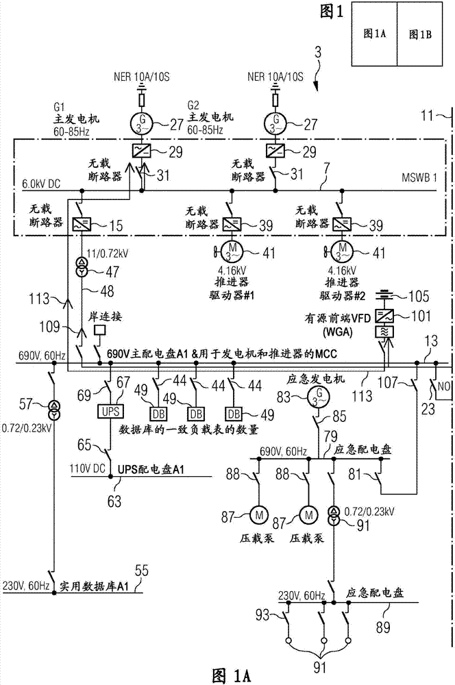
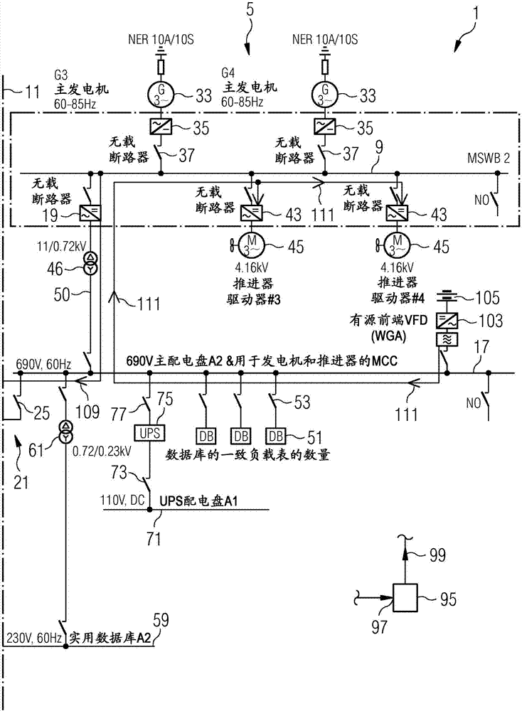
[0045] A schematic circuit diagram of a structure 1 for power distribution on a ship illustrates a first system 3 and a second system 5 sharing several features. The first system 3 comprises a first DC bus 7 operating at a first medium voltage (6.0 kVDC in the example shown). Similarly, the second system 5 comprises a second DC bus 9 operating at a second medium voltage, eg between 5kV and 10kV DC. As indicated in the figure, the first DC bus bar 7 and the second DC bus bar 9 are separated by a barrier 11 , which are independent of and / or spaced from each other. Thereby, there is no direct connection between the first DC bus 7 and the second DC bus 9 .

[0046] The first system 3 also comprises a first AC bus 13 operating at low voltage (690V, 60Hz AC in the example shown). A first inverter 15 is coupled between the first DC bus 7 and the first AC bus 13 . The second system 5 comprises a second AC bus 17 operating at low voltage (ie 690V, 60Hz AC). A second inverter 19 is ...


PUM


Abstract

Described is an arrangement (1) for power distribution on a vessel, comprising: a first DC bus (7) operating at a first medium voltage; at least one second DC bus (9) operating at a second medium voltage and having no direct connection with the first DC bus; a first AC bus (13) operating at a low voltage; a first inverter (15) coupled between the first DC bus (7) and the first AC bus (13) for allowing power flow from the first DC bus to the first AC bus in a first operation mode; a second AC bus (17) operating at the low voltage; a second inverter (19) coupled between the second DC bus (9) and the second AC bus (17) for allowing power flow from the second DC bus to the second AC bus in the first operation mode; and a low voltage connection system (21) for selectively connecting or disconnecting the first AC bus and the second AC bus.

Description

technical field [0001] The present invention relates to structures and methods for power distribution on board ships, in particular ships or platforms. Background technique [0002] In order to operate a vessel, in particular a ship or a platform such as an oil exploration platform, it is necessary to distribute power to several energy consumers. For example, propellers and pumps need to be operated on board ships. Different energy consumers require different voltages, or may require AC power or DC power. In the prior art, a medium voltage power distribution system with traditional switchgear, transformers and VFDs may have been used to provide the necessary power to multiple consumers. These traditional systems may require a stable or constant frequency. Thus, it may be desirable for the main generator or prime mover to run at a specific speed or rotational speed. In addition, all load changes must be accommodated by the prime mover. As an alternative, low voltage mult...

Claims


Application Information

Patent Timeline
Patent Type & Authority Applications(China)
IPC IPC(8): H02J3/38H02J4/00
CPCH02J3/38H02J4/00B63H23/24H02J2310/42B63H21/17H02J9/062
Inventor P·F·格杰尔佩B·哈特韦格M·希勒W·沃斯
Owner SIEMENS ENERGY AS
Why Eureka
Try Eureka