
Continuous integrated waste plastic garbage crushing and cleaning treatment device

A technology for waste plastics and processing devices, applied in plastic recycling, mechanical material recycling, recycling technology and other directions, can solve the problems of transmission conveyor belt falling off, jamming, dirty raw materials, etc., to achieve stable operation, save water resources, guarantee cleanliness effect

Inactive Publication Date: 2017-09-01
苏天平
View PDF0 Cites 25 Cited by
  • Summary
  • Abstract
  • Description
  • Claims
  • Application Information

AI Technical Summary

Problems solved by technology

Recycled plastic granules are mainly classified according to the different raw materials used and the characteristics of the processed plastic granules. During the recycling process of waste plastics, crushing work is required, and the transmission conveyor belt in the traditional crushing machine is prone to fall off, which makes it impossible to carry out normal processing. When the crushing phenomenon occurs, before many materials enter the crushing machine at the same time, it is easy to cause the phenomenon of material jamming, which affects the smoothness of crushing, and the raw materials are still very dirty and have a lot of stains, which need to be cleaned in time. The traditional manual The way of operation, the workers' work intensity is very high and the cleaning effect is very poor. When the water is removed, the water stains still adhere to the surface of the particles and need to be treated. When the particles are dried on the conveyor belt, the whole process cannot be observed by the employees in real time. It is too late to take reasonable rescue measures when a danger occurs, and it needs to be resolved

Method used


Image

  • Continuous integrated waste plastic garbage crushing and cleaning treatment device
  • Continuous integrated waste plastic garbage crushing and cleaning treatment device
  • Continuous integrated waste plastic garbage crushing and cleaning treatment device

Examples


Embodiment Construction

[0017] The following will clearly and completely describe the technical solutions in the embodiments of the present invention with reference to the accompanying drawings in the embodiments of the present invention. Obviously, the described embodiments are only some, not all, embodiments of the present invention. Based on the embodiments of the present invention, all other embodiments obtained by persons of ordinary skill in the art without making creative efforts belong to the protection scope of the present invention.

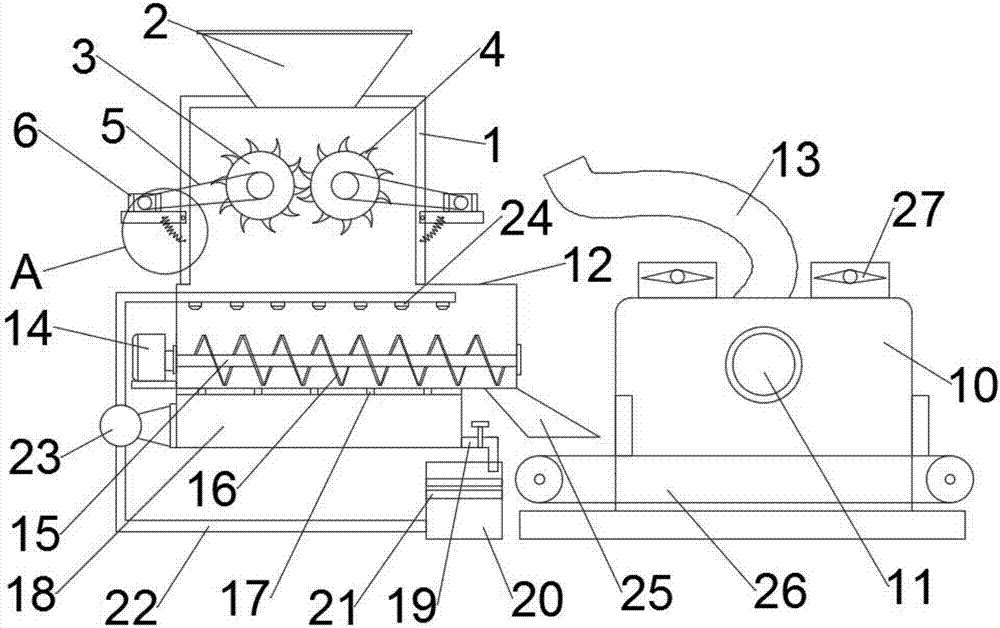
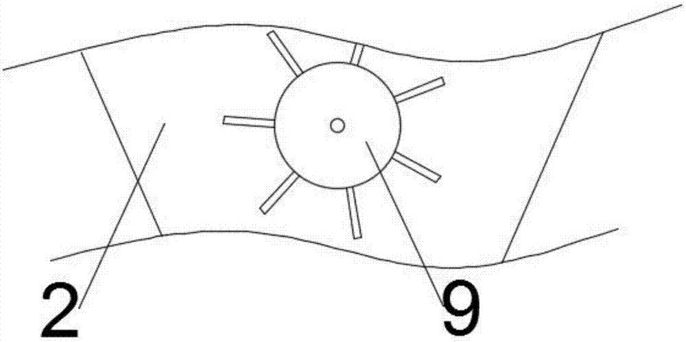
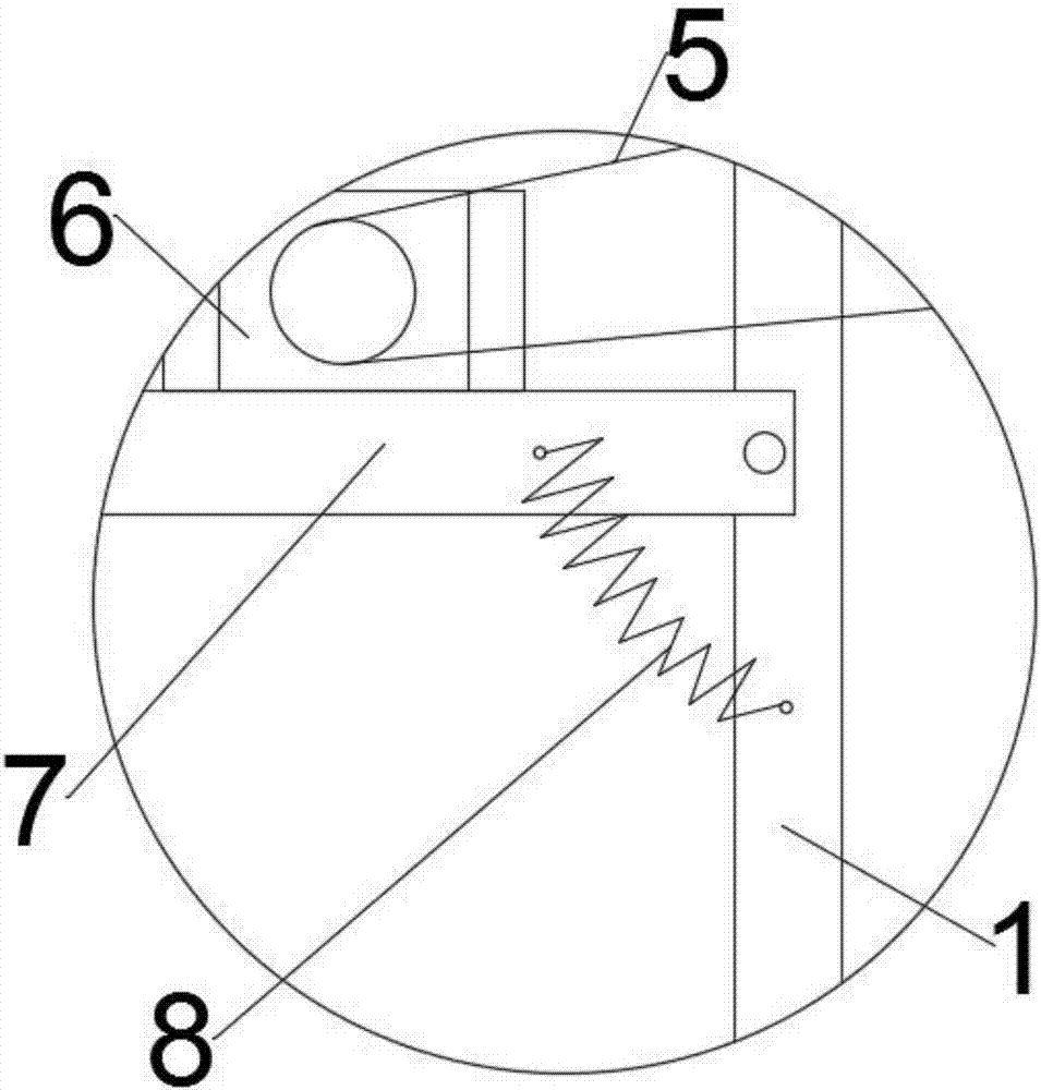
[0018] see Figure 1-3 , in the embodiment of the present invention, a continuous integrated waste plastic garbage crushing and cleaning treatment device includes a pulverizer body 1, a feeding hopper 2 is arranged on the top of the pulverizer body 1, and a dial is arranged inside the feeding hopper 2. A material turntable 9, a pair of rotating round rollers 3 are arranged in parallel in the middle of the inner cavity of the pulverizer body 1, and several pulv...


PUM


Abstract

The invention discloses a continuous integrated waste plastic garbage crushing and cleaning treatment device. The device comprises a crushing machine body; a feed hopper is arranged at the top of the crushing machine body; a poking turntable is arranged in the feed hopper; a pair of rotating circular rollers is arranged in the middle position of an inner cavity of the crushing machine body in parallel; a movable support plate is hinged to the outer side wall, opposite to the rotating circular rollers, of the crushing machine body; a transmission motor is mounted above the movable support plate; an output shaft of the transmission motor is connected to center rotating shafts of the rotating circular rollers through transmission conveying belts; and the top position of a box body of a quick drying box communicates with a water vapor discharge pipe. The transmission motor enables the transmission conveying belts to always keep in a tensioned state through self weight and tension of a powerful tension spring; and dissipated water vapor is discharged through the water vapor discharge pipe, so that subsequent finished products are directly used in a dried state.

Description

technical field [0001] The invention relates to the related technical field of waste materials processing machinery, in particular to a continuous integrated waste plastic garbage crushing and cleaning device. Background technique [0002] Plastic is a high molecular compound polymerized by addition polymerization or polycondensation reaction with monomer as raw material. It is commonly known as plastic or resin. It can freely change its composition and shape. , Colorants and other additives. Recycled plastic granules are mainly classified according to the different raw materials used and the characteristics of the processed plastic granules. During the recycling process of waste plastics, crushing work is required, and the transmission conveyor belt in the traditional crushing machine is prone to fall off, which makes it impossible to carry out normal processing. When the crushing phenomenon occurs, before many materials enter the crushing machine at the same time, it is e...

Claims


Application Information

Patent Timeline
Patent Type & Authority Applications(China)
IPC IPC(8): B29B17/00B29B17/04
CPCB29B17/00B29B17/04B29B2017/0015B29B2017/044Y02W30/52Y02W30/62
Inventor 苏天平
Owner 苏天平
Learn More