

Radio frequency amplifying system and heat radiating device thereof
A technology of radio frequency amplification and heat dissipation device, which is applied in the direction of modification through conduction and heat transfer, cooling/ventilation/heating transformation, electrical components, etc., which can solve the problem of reducing current stress and dispersing heat sources, heavy weight of radio frequency amplification system, and the number of components used. Many other problems, to achieve the effect of increasing practicability, high conversion efficiency and light weight
- Summary
- Abstract
- Description
- Claims
- Application Information
AI Technical Summary
Problems solved by technology
Method used
Image


Examples
Embodiment Construction
[0039] The detailed description and technical content of the present invention are described below with the accompanying drawings, but the attached drawings are only for reference and illustration, and are not used to limit the present invention.
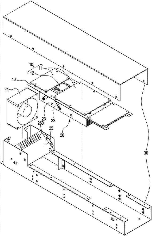
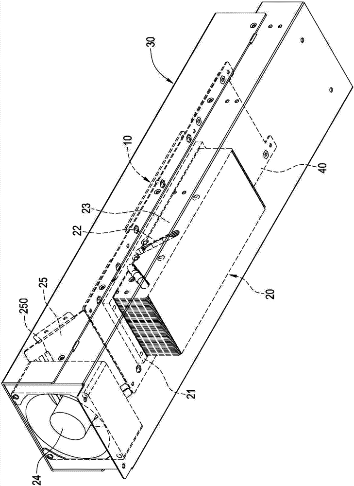
[0040] see Figure 1 to Figure 3 , are respectively the three-dimensional exploded schematic diagram of the radio frequency amplification system and its heat dissipation device of the present invention and the three-dimensional appearance schematic diagram of the two sides. The present invention provides a radio frequency amplification system and its heat dissipation device, including a radio frequency amplifier 10 and a heat dissipation device 20 . The heat dissipation device 20 is thermally connected to the RF amplifier 10 and dissipates heat from the RF amplifier 10 to prevent the operating temperature of the RF amplifier 10 from being too high, thereby maintaining the normal operation and service life of the RF amplifier 10 .
...
PUM
 Abstract
Description
Claims
Application Information