Shifting register and grid driving circuit and driving method thereof and liquid crystal display device

A shift register, circuit technology, applied in static memory, static indicator, digital memory information and other directions, can solve the problems of jitter switch, flicker, afterimage, etc., to avoid the effect of afterimage

Active Publication Date: 2017-09-05
BOE TECH GRP CO LTD +1
View PDF10 Cites 24 Cited by
  • Summary
  • Abstract
  • Description
  • Claims
  • Application Information

AI Technical Summary

Problems solved by technology

Insufficient charging and discharging time may cause charge residue in the liquid crystal capacitor and storage capacitor, which may cause afterimage, jitter, and flicker when switching on and off

Method used


Image

  • Shifting register and grid driving circuit and driving method thereof and liquid crystal display device
  • Shifting register and grid driving circuit and driving method thereof and liquid crystal display device
  • Shifting register and grid driving circuit and driving method thereof and liquid crystal display device

Examples


Embodiment Construction

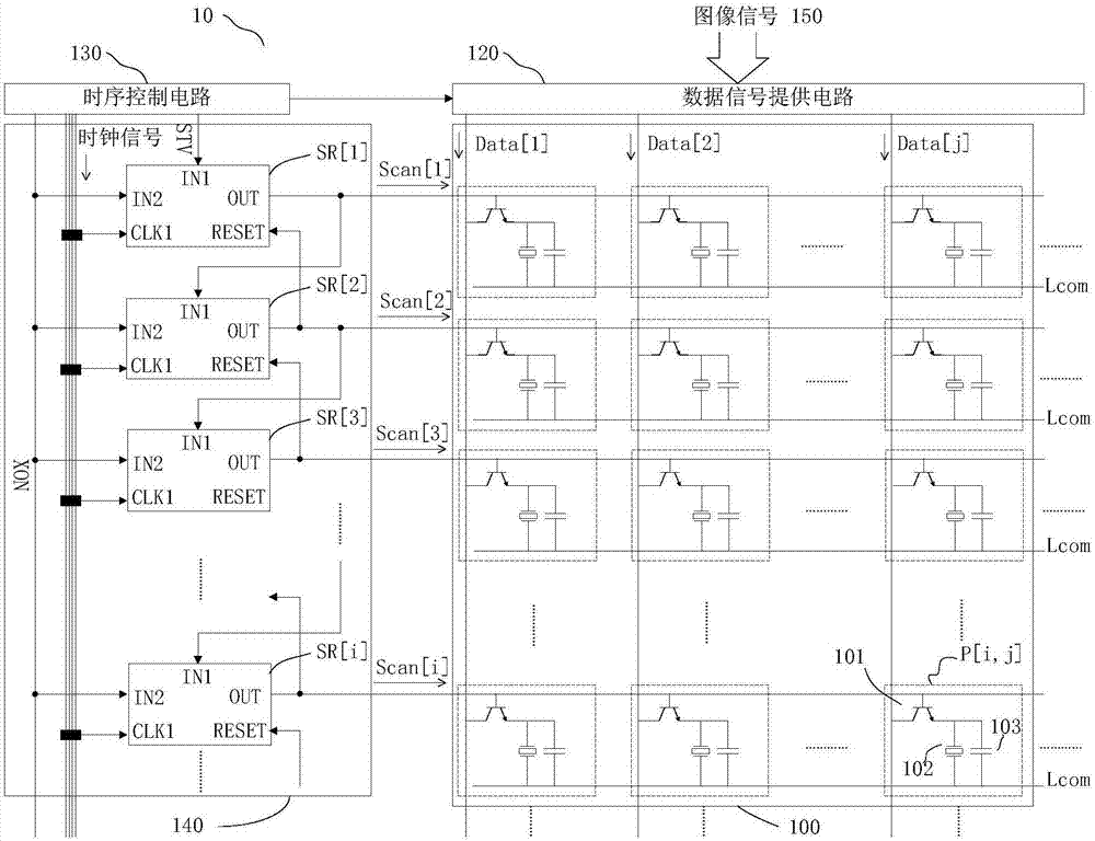
[0026] figure 1 An example of the configuration of the liquid crystal display 10 according to the embodiment of the present disclosure is shown. in such as figure 1 In the liquid crystal display 10 shown, the data signal supply circuit 120 receives the image signal 150, and transmits the data signals Data[1], Data[2], ..., Data[j] (j is a positive integer) via corresponding data lines ) ... are respectively provided to a plurality of pixels arranged on each column in the display area 100 . The gate drive circuit 140 is connected to the timing control circuit 130 to receive the required clock signal and signals such as the frame start signal STV and the control signal XON, and transmits the gate drive signal Scan[1], Scan[2], . . . , Scan[i] . . . are respectively provided to a plurality of pixels arranged on each row in the display area 100 .

[0027] Such as figure 1 As shown, the gate driving circuit 140 includes a plurality of shift registers SR[1], SR[2], . . . , SR[i]...


PUM


Abstract

The invention provides a shifting register and a grid driving circuit and a driving method thereof and a liquid crystal display device. The shifting register comprises a pull-up sub-circuit, a first output sub-circuit, a reset sub-circuit and a second output sub-circuit, wherein when a first input end receives first input signals, the pull-up sub-circuit sets the potential of a pull-up node as a wording potential; when the potential of the pull-up node is the working potential, the first output sub-circuit outputs grid driving signals at an output end according to first clock signals which are received by a first clock signal end; when reset signals are received by a reset end, the reset sub-circuit sets the potential of the pull-up node and the output end as reset potential; when second input signals are received by a second input end, the second output sub-circuit outputs the grid driving signals at the output end in the time bucket apart from the period of displaying a one frame picture.

Description

technical field [0001] The present disclosure relates to a shift register, a gate driving circuit and a driving method thereof, and a liquid crystal display. Background technique [0002] Liquid crystal displays display images by continuously deflecting liquid crystals. Liquid crystals generally have capacitance parameters, and the equivalent capacitance of liquid crystals is also called liquid crystal capacitance. In addition, a storage capacitor is usually provided between the pixel electrode and the common electrode to help maintain the voltage that deflects the liquid crystal. The liquid crystal is deflected according to the charge stored in the liquid crystal capacitor and the storage capacitor. [0003] In the process of displaying different pictures, the liquid crystal capacitor and the storage capacitor will be charged and discharged many times. As the refresh rate of the display device increases, the charging and discharging of the liquid crystal capacitor and th...

Claims


Application Information

Patent Timeline
Patent Type & Authority Applications(China)
IPC IPC(8): G09G3/36G11C19/28
CPCG09G3/3674G11C19/28G09G2310/0286G09G2310/063G09G2310/08G09G3/3648G09G3/3677G09G2310/062
Inventor 胡胜华聂春扬闫冰冰
Owner BOE TECH GRP CO LTD
Why Eureka
Try Eureka