Millimeter wave space power divider and millimeter wave space power combiner

A technology of power divider and millimeter wave, which is applied in the direction of waveguide devices, electrical components, connecting devices, etc., and can solve the problems of large insertion loss, small power capacity, unfavorable power distribution/combiner miniaturization design in the millimeter wave band, etc.

Active Publication Date: 2017-09-05
NINGBO UNIV
View PDF3 Cites 14 Cited by
  • Summary
  • Abstract
  • Description
  • Claims
  • Application Information

AI Technical Summary

Problems solved by technology

However, the power divider has the following problems: 1. The power divider is affected by isolation resistance and dielectric materials, and its power capacity is small, which is not conducive to the power distribution of high-power sources; 2. The power divider is suitable for microwave low frequency bands. The insertion loss will be larger for the millimeter wave band
All materials of this spatial power distribution / combiner are metal, with high output power, wide frequency band, and simple assembly. However, when multiplex distribution or synthesis is used, the air lens, which constitutes its core component, must be limited by a complete metal disc. The size is relatively large, the cost is high, and a large space is required, which is not conducive to the miniaturization design of the power distribution / combiner

Method used


Image

  • Millimeter wave space power divider and millimeter wave space power combiner
  • Millimeter wave space power divider and millimeter wave space power combiner
  • Millimeter wave space power divider and millimeter wave space power combiner

Examples


Embodiment 1

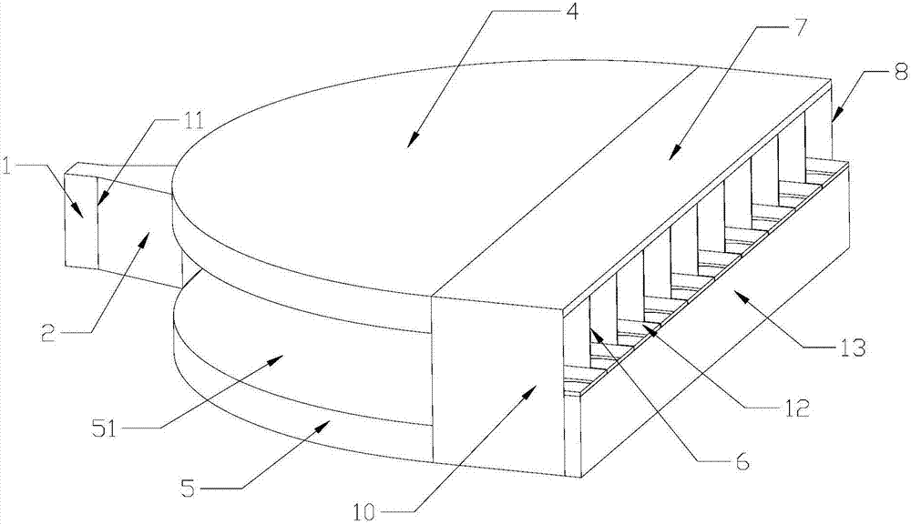
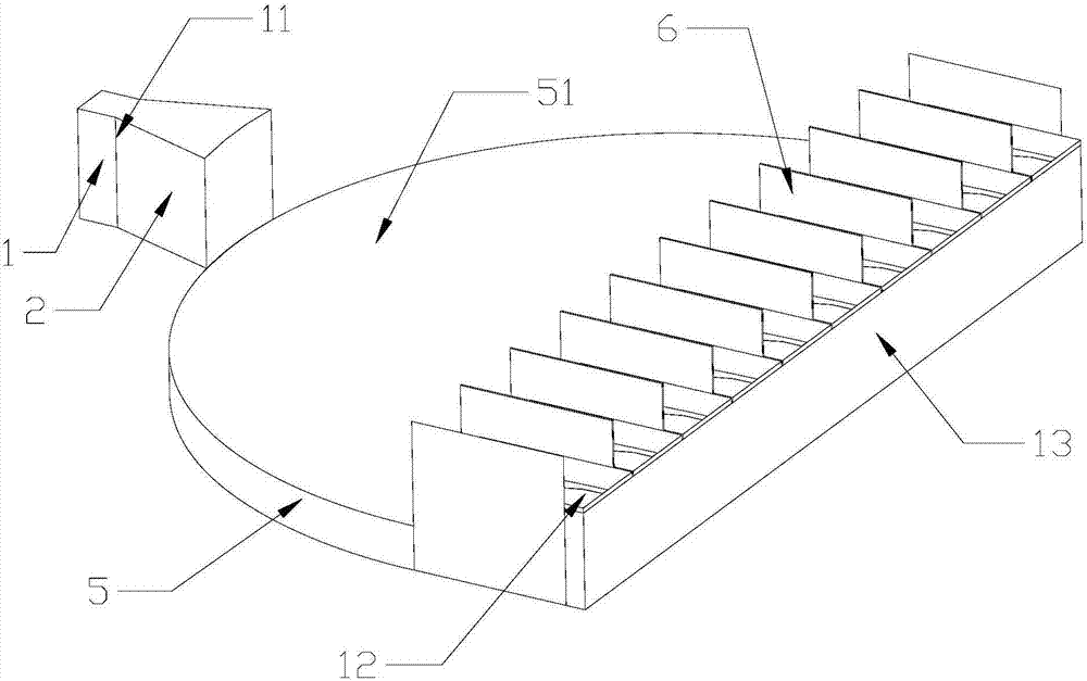
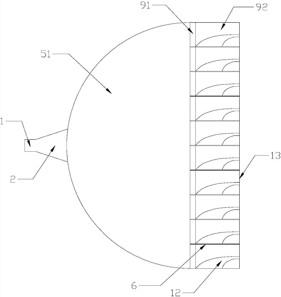
[0020] Embodiment one: if Figure 1-4 As shown, a millimeter-wave spatial power divider includes a standard rectangular waveguide 1, a transition waveguide 2, an air lens, and an output array arranged in sequence from front to back. The structure of the transition waveguide 2 is in the shape of a bell mouth. The standard rectangular waveguide 1 is connected, and the rear end of the transitional waveguide 2 intersects with the air lens. The air lens includes two metal semi-discs arranged symmetrically up and down. The metal semi-discs retain the required parts according to the principle of the improved Maxwell fisheye lens and Remove the part that the signal cannot reach and present a semi-disc shape. The principle of the improved Maxwell fisheye lens is basically the same as that of the Maxwell fisheye lens. The only difference is that the refractive index distribution function of the improved Maxwell fisheye lens is n(r )=N 0 / [1+δ(r / R) 2 ], where N 0 and δ are two adjusta...

Embodiment 2

[0022] Embodiment 2: This embodiment is basically the same as Embodiment 1, except that in this embodiment, the thickness of the high-frequency dielectric plate is equal to 20 mil.

[0023] The present invention also discloses a millimeter-wave spatial power combiner. The millimeter-wave spatial power combiner of the present invention will be further described in detail below with reference to the embodiments of the accompanying drawings.

[0024] Embodiment 1: A millimeter-wave spatial power combiner, including an input array, an air lens, a transition waveguide 2 and a standard rectangular waveguide 1 arranged in sequence from front to back, the structure of the transition waveguide 2 is in the shape of a bell mouth, and the rear of the transition waveguide 2 The end is connected with the standard rectangular waveguide 1, and the front end of the transitional waveguide 2 intersects with the air lens, which is characterized in that the air lens includes two metal half disks ar...


PUM


Abstract

The invention discloses a millimeter wave space power divider and a millimeter wave space power combiner. The millimeter wave space power divider comprises a standard rectangular waveguide, a transition waveguide, an air lens and an output array, wherein the air lens comprises two metal semicircular discs which are symmetrically arranged in the vertical direction, the metal semicircular discs reserves a required part and removes a part to which signals cannot reach according to the principle of an improved Maxwell fisheye lens so as to present a semicircular disc shape, the lower surface of the metal semicircular disc located at the upper layer and the upper surface of the metal semicircular disc located at the lower layer are concave arc-shaped surfaces with the same size, a smooth curve of each concave arc-shaped surface is decided by the principle of the improved Maxwell fisheye lens, and the concave arc-shaped surfaces of the two metal semicircular discs respectively form an improved Maxwell fisheye lens. The millimeter wave space power divider has the advantages of high output power, wide frequency band, simple assembly, small structural size, low cost and ability of realizing miniaturization.

Description

technical field [0001] The invention relates to a millimeter-wave spatial power distribution and synthesis technology, in particular to a millimeter-wave spatial power distribution / combiner. Background technique [0002] Millimeter-wave broadband high-power amplifiers are used more and more in the fields of communication, remote sensing, radar and electronic countermeasures. A variety of power combining techniques have been proposed in the microwave and millimeter wave frequency ranges in recent decades. Quasi-optical (spatial) power combining technology is a power combining method proposed in the early 1980s. In this quasi-optical or spatial power combination, the power is coupled into a large-diameter guided wave beam by an active device, and then the beam is focused to the space power demand or converted into a waveguide mode output. The large-diameter beam cross-section enables more combining elements to be used, thus providing greater output power. And all combining ...

Claims


Application Information

Patent Timeline
Patent Type & Authority Applications(China)
IPC IPC(8): H01P5/16H01P5/12
CPCH01P5/12H01P5/16
Inventor 吴章敏华昌洲
Owner NINGBO UNIV
Why Eureka
Try Eureka