
Angular velocity detection circuit, angular velocity detection device, electronic apparatus, and moving object

A technology of angular velocity detection and angular velocity, which is applied in speed/acceleration/shock measurement, navigation through speed/acceleration measurement, and measurement devices, etc. It can solve problems such as increasing S/N of difficult angular velocity signals and increasing noise components

Inactive Publication Date: 2017-09-12
SEIKO EPSON CORP
View PDF10 Cites 1 Cited by
  • Summary
  • Abstract
  • Description
  • Claims
  • Application Information

AI Technical Summary

Problems solved by technology

[0004] However, in the gyro sensor described in Patent Document 1, there is a problem that when capacitive coupling is performed before the detection circuit, the noise component included in the signal input to the detection circuit increases, making it difficult to detect S / N improvement of the output angular velocity signal

Method used


Image

  • Angular velocity detection circuit, angular velocity detection device, electronic apparatus, and moving object
  • Angular velocity detection circuit, angular velocity detection device, electronic apparatus, and moving object
  • Angular velocity detection circuit, angular velocity detection device, electronic apparatus, and moving object

Examples


Embodiment Construction

[0068] Hereinafter, preferred embodiments of the present invention will be described in detail with reference to the drawings. In addition, the embodiment described below is not an aspect which unduly limits the content of this invention described in a claim. In addition, not all the configurations described below are necessarily essential configuration requirements of the present invention.

[0069] 1. Angular velocity detection device

[0070] 1-1. First Embodiment

[0071] Structure and operation of angular velocity detection element

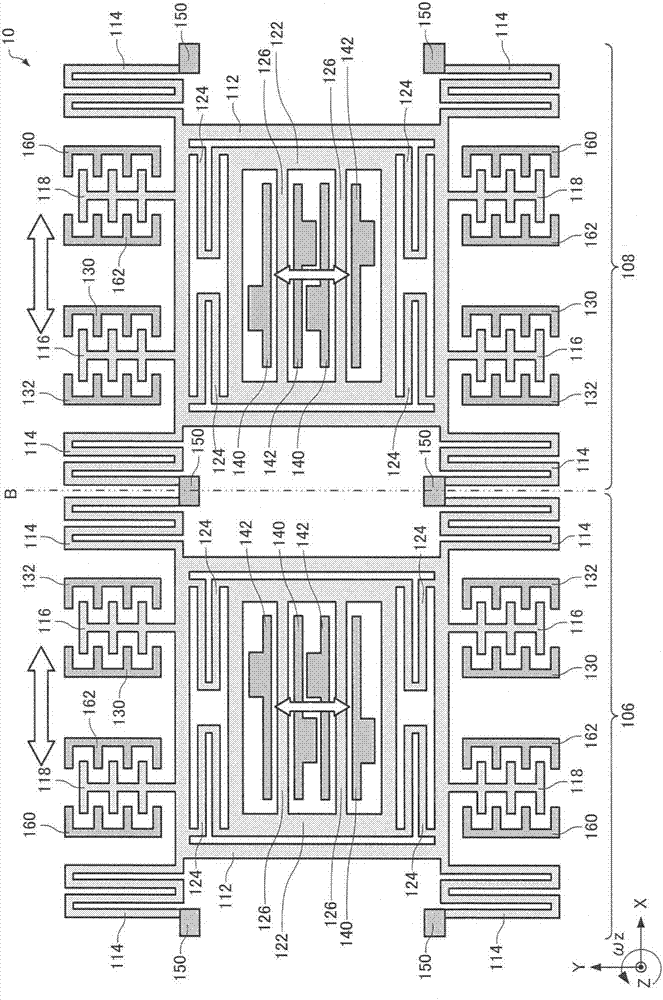
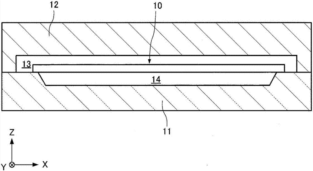
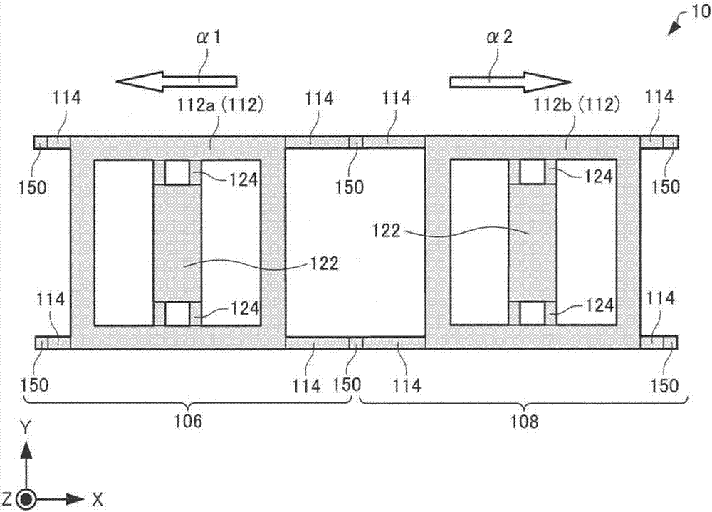
[0072] First, the angular velocity detection element 10 included in the angular velocity detection device 1 according to the present embodiment will be described with reference to the drawings. figure 1 It is a top view schematically showing the angular velocity detection element 10 . figure 2 It is a cross-sectional view schematically showing the angular velocity detection element 10 . In addition, in figure 1 In FIG. 3 , X-axis, Y-ax...


PUM


Abstract

The invention provides an angular velocity detection circuit, an angular velocity detection device, an electronic apparatus, and a moving object. The angular velocity detection circuit includes: a first conversion unit that includes a first operational amplifier, and converts a first detection signal, which is output from a first detection electrode and is input to a first input terminal of the first operational amplifier, into a voltage; an angular velocity signal generation unit that generates an angular velocity signal on the basis of an output signal of the first conversion unit; and a first correction signal generation unit that generates a first correction signal for reducing an offset of the angular velocity signal which occurs due to a leakage signal included in the first detection signal on the basis of a signal based on drive oscillation of the angular velocity detection element. The first correction signal is input to the first input terminal or a second input terminal of the first operational amplifier directly or through a resistor.

Description

technical field [0001] The invention relates to an angular velocity detection circuit, an angular velocity detection device, electronic equipment and a moving body. Background technique [0002] In recent years, an angular velocity sensor (gyro sensor) that detects angular velocity using, for example, silicon MEMS (Micro Electro Mechanical System: Micro Electro Mechanical System) technology has been developed. [0003] Patent Document 1 discloses a method for reducing the quadrature error contained in the output signal of the detection main section by inputting a quadrature error canceling signal to the front stage of the detection circuit (between the detection main section and the C / V conversion circuit) by capacitive coupling. Signal technology. [0004] However, in the gyro sensor described in Patent Document 1, there is a problem that when capacitive coupling is performed before the detection circuit, the noise component included in the signal input to the detection ci...

Claims


Application Information

Patent Timeline
IPC IPC(8): G01C19/5776G01C21/18
CPCG01C19/5776G01C21/18G01C19/5726G01C19/5712
Inventor 金本啓
Owner SEIKO EPSON CORP
Learn More