Hybrid power system and control method based on self-diagnosis electromagnetic jaw clutch

A technology of jaw clutches and hybrid power systems, applied in the direction of magnetic drive clutches, clutches, non-mechanical drive clutches, etc., can solve the problems of vehicle dynamic performance disorder, strong electromagnetic interference, high dust and metal debris content, and achieve The effect of compact structure and mature structure

Pending Publication Date: 2017-09-15
BIT HUACHUANG ELECTRIC VEHICLE TECH
View PDF13 Cites 6 Cited by
  • Summary
  • Abstract
  • Description
  • Claims
  • Application Information

AI Technical Summary

Problems solved by technology

However, the application of the electromagnetic jaw clutch in the field of hybrid power transmission technology is still immature, and basically the electromagnetic clutch in the traditional industrial field is directly copied to the hybrid power transmission system, or only its basic structure is modified. Shape improvement
Therefore, the existing electromagnetic clutch of this kind of transmission quality cannot adapt to the complex and changeable environment during vehicle transmission at all. What is important is that it does not have an accurate and efficient feedback mechanism that can display the clutch engagement state, so it cannot judge the clutch in real time. Engaged state, that is, the existing vehicle control methods are all based on the assumption that the clutch will be fully engaged, which obviously does not meet the basic requirements of vehicle safety
Facts have proved that the use of electromagnetic jaw clutches with simple functions cannot meet the transmission needs of hybrid vehicles. The power supply of the electromagnetic coil cannot be strictly guaranteed to be stable; second, the drive train of a hybrid vehicle has been working in a complex environment of high-speed rotation and vibration for a long time, and there is a high content of dust and metal debris near it. Once these impurities are magnetized, they will It will be adsorbed on the periphery of the armature and the electromagnetic coil, thereby hindering the mutual attraction between the driving disc and the driven disc; third, the separation device of the electromagnetic jaw clutch mainly uses a compression spring, a diaphragm spring or a wave plate, etc., and its essence is uniform. It is a mechanical elastic element. When the electromagnetic coil is powered off, it is impossible to confirm whether the main and driven parts of the clutch have been really separated; fourth, the attraction of the electromagnetic coil and the armature can only prove the correct engagement state of the clutch in the axial direction, and It cannot reflect whether the driving and driven parts are correctly transmitting the torque, such as the teeth hitting at the moment of engagement, or the clutch is prone to slipping and throwing off when the teeth are worn out. Once any of the above technical problems occurs, the vehicle control When the VCU cannot get feedback, the whole vehicle will still output torque according to the predetermined control logic. This kind of loading in the state of technical failure will cause great harm to the transmission system and make the power performance of the whole vehicle disordered. There is a big security risk
However, the electromagnetic tooth clutch described in this invention is not equipped with an accurate and efficient feedback structural component capable of displaying the clutch engagement state, so this technical solution cannot judge the real-time engagement state of the clutch, and its vehicle control method is still based on a certain clutch. Based on the assumption that it will be completely absorbed, it obviously does not meet the basic requirements of vehicle safety, so it needs to be improved urgently

Method used


Image

  • Hybrid power system and control method based on self-diagnosis electromagnetic jaw clutch
  • Hybrid power system and control method based on self-diagnosis electromagnetic jaw clutch
  • Hybrid power system and control method based on self-diagnosis electromagnetic jaw clutch

Examples


Embodiment Construction

[0040] This embodiment is only a preferred technical solution, and the various components and connection relationships involved are not limited to the following implementation described in this embodiment. The configuration and connection relationship of the various components in the preferred solution can be Carry out arbitrary permutations and combinations to form a complete technical solution.

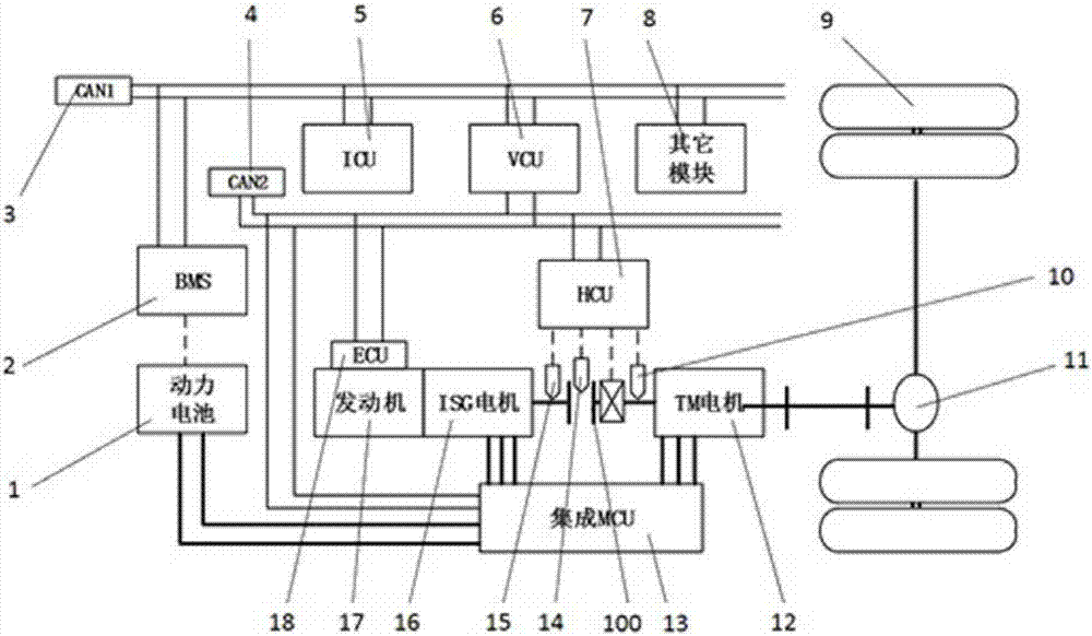
[0041] Combine below Figure 1-5 Describe in detail the technical solution of the hybrid power system based on the self-diagnosing electromagnetic jaw clutch:

[0042] A hybrid power system based on a self-diagnosing electromagnetic jaw clutch, including an engine 17, a power generation and starting integrated motor 16, a main drive motor 12 and a clutch assembly 100, the engine 17 is connected to the power generation and starting integrated motor 16, and the power generation and starting integrated motor 16 is connected with the main drive motor 12 through the clutch assembly 100,...


PUM


Abstract

The invention relates to a hybrid power system and a control method based on a self-diagnosis electromagnetic jaw clutch. The hybrid power system comprises an engine (17), a generating starting integrated motor (16), a main drive motor (12) and a clutch assembly (100), wherein the engine (17) is connected with the generating starting integrated motor (16); the generating starting integrated motor (16) is connected with the main drive motor (12) through the clutch assembly (100); the generating starting integrated motor (16) comprises an ISG motor output shaft (106); the clutch assembly (100) adopts a self-diagnosis electromagnetic jaw clutch; and the self-diagnosis electromagnetic jaw clutch comprises a self-diagnosis feedback structural component. The control method comprises three-stage self-diagnosis control methods, successively including a first-stage control end diagnosis control method, a second-stage position end diagnosis control method and a third-stage rotational speed end diagnosis control method. Compared with the prior art, the hybrid power system and the control method based on a self-diagnosis electromagnetic jaw clutch disclosed by the invention have the beneficial effects that the engagement state of the clutch is accurately fed back and the high-safety requirement of a vehicle is met.

Description

technical field [0001] The invention relates to a hybrid power system and a control method for an electric vehicle, in particular to a hybrid power system and a control method based on a self-diagnosing electromagnetic jaw clutch. Background technique [0002] In the field of new energy vehicle electric drive technology, hybrid power system has always been a hot spot in research and development. Most hybrid transmission configurations are designed with an engine-dual-motor hybrid system, that is, the engine is connected to the Integrated Starter and Generator (ISG) and then connected to the main drive motor (Traction Motor, TM). . There is a clutch device between the ISG motor and the TM motor, and the switching of the pure electric, series or parallel driving modes of the dual-motor hybrid system is realized through the separation and engagement of the clutch device. [0003] At present, in the field of new energy hybrid technology, the engine integrated ISG motor assembl...

Claims


Application Information

Patent Timeline
Patent Type & Authority Applications(China)
IPC IPC(8): B60K6/38B60R16/02F16D27/09F16D27/14
CPCF16D27/09F16D27/14B60K6/38B60R16/02F16D2300/18
Inventor 林程周辉时军辉董爱道赵明杰
Owner BIT HUACHUANG ELECTRIC VEHICLE TECH
Why Eureka
Try Eureka