Venturi tube based high-flux hydraulic cavitation reactor and cavitation method

A Venturi, high-flux technology, applied in the direction of mechanical oscillation water/sewage treatment, etc., can solve the problem of insufficient triggering or strengthening of physical and chemical reactions, large pipeline structure of the treatment system, and the processing capacity of the cavitation reactor. Small problems, etc., to achieve the effect of improving energy utilization, low equipment manufacturing cost, and reducing turbulent non-uniformity

Active Publication Date: 2017-09-15
RES INST OF PHYSICAL & CHEM ENG OF NUCLEAR IND
View PDF13 Cites 13 Cited by
  • Summary
  • Abstract
  • Description
  • Claims
  • Application Information

AI Technical Summary

Problems solved by technology

[0006] Although the research on hydrodynamic cavitation has gradually deepened, and the number of cavitator structures proposed has increased, the cavitation intensity and efficiency of hydrodynamic cavitation are relatively low, which is often not enough to trigger or intensify certain physical and chemical reactions.
In addition, the processing capacity of the cavitation reactor is small, and multiple devices need to be used in parallel or in series for large-scale processing, resulting in a large and complex pipeline structure of the processing system, which is still difficult to promote and apply industrially

Method used


Image

  • Venturi tube based high-flux hydraulic cavitation reactor and cavitation method
  • Venturi tube based high-flux hydraulic cavitation reactor and cavitation method
  • Venturi tube based high-flux hydraulic cavitation reactor and cavitation method

Examples


Embodiment 1

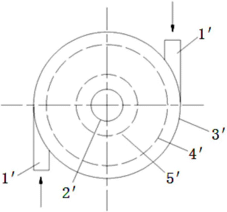
[0044] Such as figure 1 As shown, a large-flux hydraulic cavitation generator based on a Venturi tube includes a fluid inlet pipe (1'), a fluid outlet pipe (2'), a cylindrical cavity (3'), an annular orifice (including Class I annular orifice plate (4'), class II annular orifice plate (5', etc.) and cavitation enhancement module (6').

[0045] The first-level annular orifice plate (4') and the second-level annular orifice plate (5') are coaxially arranged in the cylindrical cavity (3'), and the center of the cylindrical cavity (3') is provided with a hollow Enhancement module (6'), two fluid inlet pipes (1') connected with the cylindrical cavity (3') are respectively arranged on the left and right sides of the cylindrical cavity (3'), and the two fluid inlets The tube (1') is arranged on the tangential direction of the outer edge of the cylindrical cavity (3'), and the fluid outlet tube (2') is arranged concentrically at the top or the upper and lower sides of the center of t...

Embodiment 2

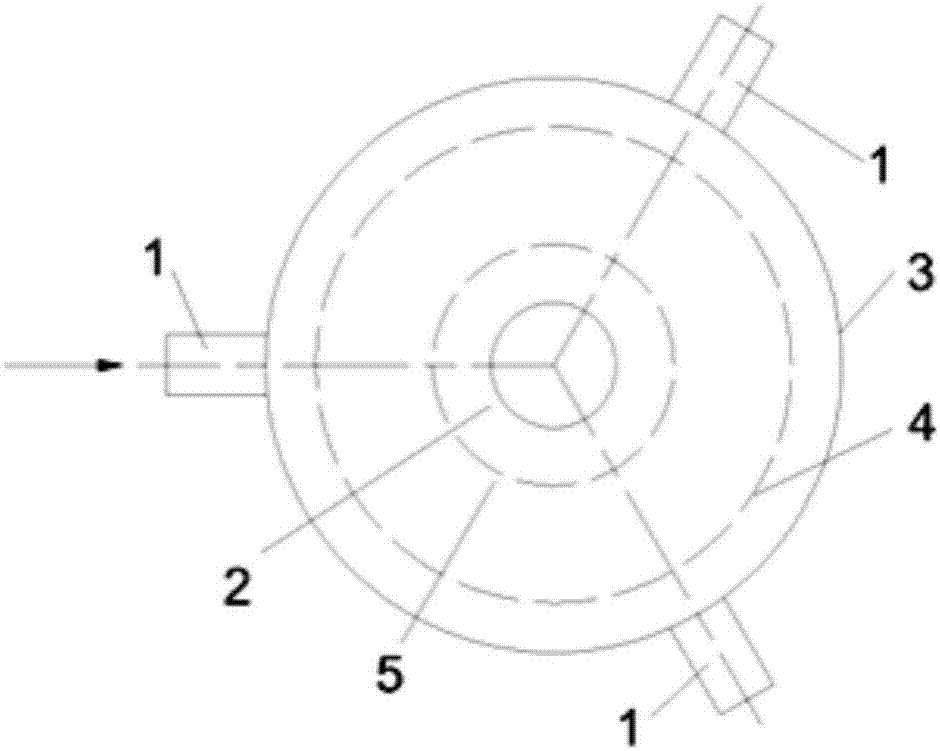
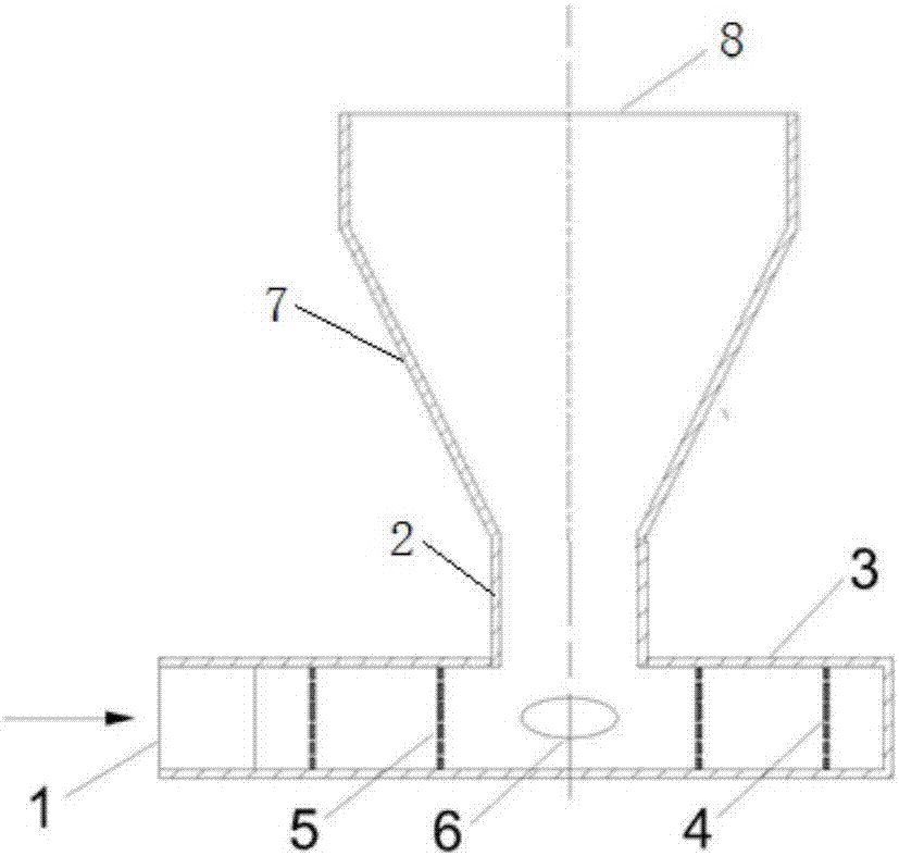
[0048] Such as Figure 2-4 , a large-flux hydraulic cavitation generator based on a Venturi tube, comprising a fluid inlet pipe (1), a fluid outlet pipe (2), a cylindrical cavity (3), an annular orifice (including a first-stage annular orifice (4), a second-level annular orifice plate (5), etc.) and a cavitation enhancement module (6).

[0049] The first-level annular orifice plate (4) and the second-level annular orifice plate (5) are coaxially arranged in the cylindrical cavity (3), and the center of the cylindrical cavity (3) is provided with a cavitation enhancement module ( 6), three fluid inlet pipes (1) are evenly arranged on the normal direction of the outer edge of the cylindrical cavity (3), and the fluid outlet pipes (2) are arranged concentrically on the cylindrical cavity (3) The upper end or upper and lower ends of the center position.

[0050] Venturi tube structure, including expansion section (7) and liquid outlet section (8), the small-diameter end of the b...


PUM

PropertyMeasurementUnit
porosityaaaaaaaaaa

Abstract

The invention discloses a venturi tube based high-flux hydraulic cavitation reactor and a hydraulic cavitation method. The reactor comprises a cylindrical cavity, a plurality of fluid inlet pipes, an annular porous plate, a fluid outlet pipe and a venturi tube structure. The fluid inlet pipes are uniformly arranged at the outer edge of the cylindrical cavity, the annular porous plate is coaxially arranged in the cylindrical cavity, the fluid outlet pipe is arranged at the axis position of the cylindrical cavity, and the venturi tube structure is arranged on the fluid outlet pipe. The hydraulic cavitation method includes steps: fluid enters a cavity between the annular porous plate and the outer wall of the cylindrical cavity along the fluid inlet pipes; the fluid penetrates the annular porous plate; after the fluid passes through the annular porous plate, a great quantity of cavitation bubbles are generated, and a strong cavitation phenomenon is generated by convergence and collision of cavitation fluid at the center of the cylindrical cavity; treated fluid enters an expansion section through the fluid outlet pipe and gradually recovered in pressure along with expansion of a flowing passage, and the cavitation bubbles collapse again to form micro jet flow and shock wave to generate instantaneous local high temperature and instantaneous high pressure. The venturi tube based high-flux hydraulic cavitation reactor and the hydraulic cavitation method have advantages of high flux and high cavitation efficiency.

Description

technical field [0001] The invention relates to the technical field of chemical fluids, in particular to a Venturi tube-based large-flux hydraulic cavitation generator and a cavitation method. Background technique [0002] Cavitation refers to the process of the formation, development and collapse of gas cavities inside the liquid or on the liquid-solid interface when the local pressure in the liquid drops. When the liquid pressure drops to even below the saturated vapor pressure of the liquid, a large number of cavitation bubbles are generated due to the violent vaporization of the liquid. Cavitation bubbles expand and grow with liquid flow. When the liquid pressure recovers, the cavitation bubbles collapse instantly to form micro jets and shock waves, resulting in instantaneous local high temperature (1000-5000K) and instantaneous high pressure (1-5×10⁷Pa). Cavitation can lead to performance degradation of hydraulic mechanical equipment, causing vibration, noise, and cav...

Claims


Application Information

Patent Timeline
Patent Type & Authority Applications(China)
IPC IPC(8): C02F1/34
CPCC02F1/34
Inventor 魏世超梅越民张凯
Owner RES INST OF PHYSICAL & CHEM ENG OF NUCLEAR IND
Why Eureka
Try Eureka