IGBT drive signal hardware interlocking and dead zone setting circuit

A technology for driving signals and hardware, applied in the electrical field, can solve the problems of reducing output efficiency, output waveform distortion, large dead time, etc., to avoid the risk of shoot-through and improve the level of safety.

Inactive Publication Date: 2017-09-15
华域汽车电动系统有限公司
View PDF3 Cites 7 Cited by
  • Summary
  • Abstract
  • Description
  • Claims
  • Application Information

AI Technical Summary

Problems solved by technology

The dead time is large, and the module works more reliably, but it will cause distortion of the output waveform and reduce the output efficiency

Method used


Image

  • IGBT drive signal hardware interlocking and dead zone setting circuit
  • IGBT drive signal hardware interlocking and dead zone setting circuit
  • IGBT drive signal hardware interlocking and dead zone setting circuit

Examples


Embodiment 1

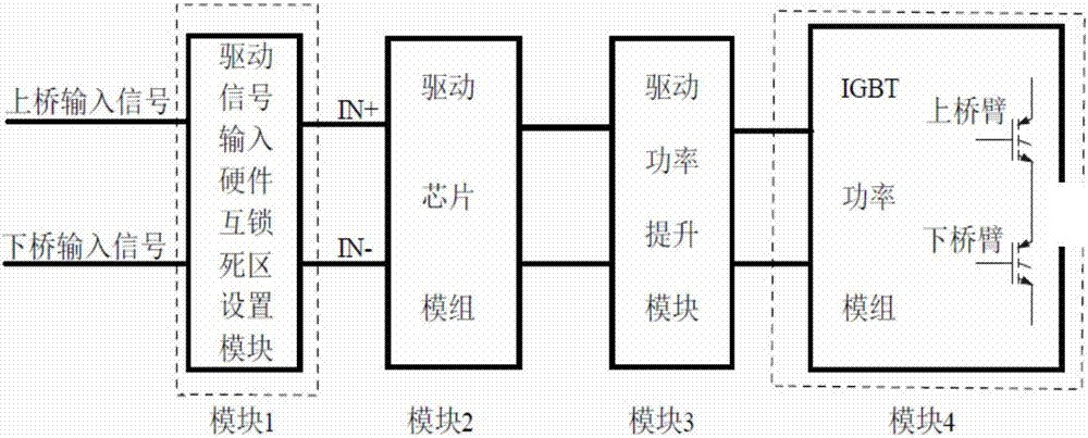
[0016] Such as figure 1 Shown is the block diagram of the IGBT drive system. Module 1 represents the input signal processing module and the IGBT drive signal interlock and hardware dead zone setting circuit. Module 2 represents the driver chip module. Module 3 represents the drive power boost module. Module 4 represents the IGBT module. .

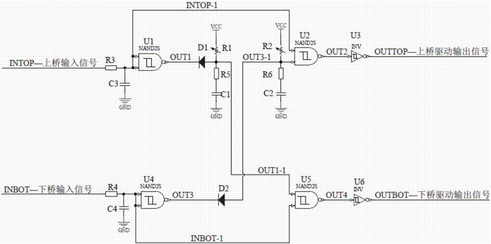
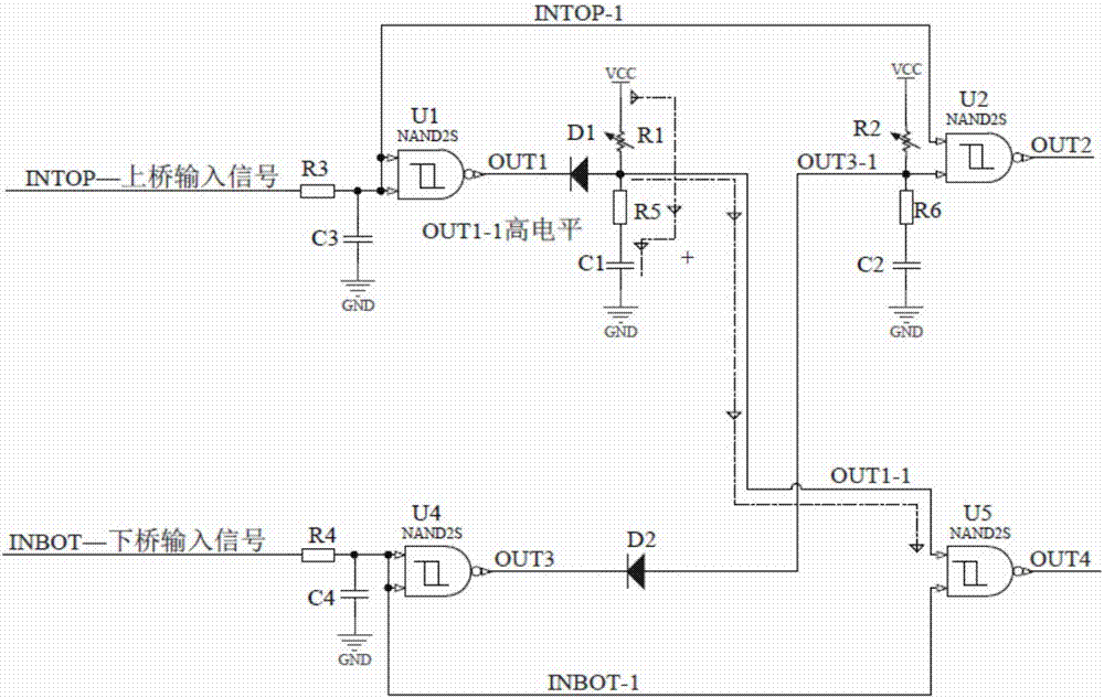
[0017] Such as figure 2 , image 3 and Figure 4 As shown, the IGBT drive signal hardware interlock and dead zone setting circuit of the present invention includes a first pull-up resistor R1, a second pull-up resistor R2, a third resistor R3, a fourth resistor R4, a first Fifth resistor R5, sixth resistor R6, first capacitor C1, second capacitor C2, third capacitor C3, fourth capacitor C4, first diode D1, second diode D2, first NAND gate Chip U1, the second NAND chip U2, the third NAND chip U3, the fourth NAND chip U4, the fifth NAND chip U5 and the sixth NAND chip U6, wherein the upper bridge input signal INTOP is connected to the t...


PUM


Abstract

The invention discloses an IGBT drive signal hardware interlocking and dead zone setting circuit, and the circuit comprises two pull-up resistors, four resistors, four capacitors, two diodes, four NAND gate chips, and two NOT gate chips. The circuit is mainly achieved through a Schmidt NAND gate chip and a Schmidt NOT gate chip, and the dead zone setting is mainly implemented through a timing resistor and a capacitor. When the dead zone time between an upper bridge input signal and a lower bridge input signal of the circuit is greater than the dead zone time of circuit setting, a system neglects the dead zone time of the circuit, and gives the dead zone time according to the dead zone time set by the system. When the dead zone time between the upper bridge input signal and the lower bridge input signal of the circuit is less than the dead zone time of circuit setting, the system forcedly gives the dead zone time according to the set minimum dead zone time, thereby integrating the IGBT drive, and improving the function safety level of a whole control system in a safer and more effective manner.

Description

Technical field: [0001] The invention relates to the electrical field, in particular to inverter technology, in particular to an IGBT drive signal hardware interlock and dead zone setting circuit. Background technique: [0002] IGBT—Insulated Gate Transistor, with its advantages of high operating voltage, large operating current, high switching frequency, and simple drive circuit, has become the most widely used power electronic switching element in the field of medium and large power inverters. IGBT modules have gradually become the first choice for inverter power components due to their internal packaging of multiple IGBT monomers, small size, high power density, and easy assembly. [0003] The dead time is mainly for the IGBT switching tube. Ideally, the IGBT of the single bridge arm of the inverter is always turned on and off in a complementary manner. Since there is a certain junction capacitance in power devices such as IGBTs, it will cause delays in the turn-on and t...

Claims


Application Information

Patent Timeline
Patent Type & Authority Applications(China)
IPC IPC(8): H02M1/38
CPCH02M1/38
Inventor 李大伟马岭杨文杰竺仁杰徐锋
Owner 华域汽车电动系统有限公司
Why Eureka
Try Eureka